Member
Joined 2009
Paid Member
It's $18.61 for a pack of 10 letter size sheets. Haven't used it before so can't vouch for it. It's made by Puslar which seems to be a known entity.
Had a crisis of confidence with the pcb, the design I have doesn't make it easy to replace parts because of how the heatsink is positioned along the underside of the board (allows boards to be stacked on edge inside the box). I'm not designing it with commercial ease-of-service in mind but to address this now would mean moving the heatsink so that it's along one edge of the board and laying out the whole thing again. On the other hand, I could probably arrange to mount the rectifier diodes on the heatsink if I did that
Had a crisis of confidence with the pcb, the design I have doesn't make it easy to replace parts because of how the heatsink is positioned along the underside of the board (allows boards to be stacked on edge inside the box). I'm not designing it with commercial ease-of-service in mind but to address this now would mean moving the heatsink so that it's along one edge of the board and laying out the whole thing again. On the other hand, I could probably arrange to mount the rectifier diodes on the heatsink if I did that
Bigun said:It's $18.61 for a pack of 10 letter size sheets. Haven't used it before so can't vouch for it. It's made by Puslar which seems to be a known entity.
Hi Gareth,
Progress looks good

I use (with excellent results) the cheap photo paper from Staples as recommended by Tom Gootee - 100 sheets for $30.00. I've used quite a few over the last year, more than 40.
You may want to build your prototype on perf board to work out the small bugs that are bound to show up.
Member
Joined 2009
Paid Member
It's been 30 years since I played with perf board ! It's a good suggestion, but I'm not too afraid to botch up the first pcb, it's only money afterall ")
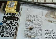
The pcb design was too large to fit on a single letter size print out, so I've squashed it down to a size that's easy to deal with. It ain't finalized and checked over yet, but we're getting there...
I'm going to be stuck waiting for a few back ordered parts from DigiKey (e.g PSU caps). This gives me time to set things up, make a first-go pcb, sort out the chasis and heatsink.
I'm thinking the first step is to build the psu, check it. Then build the simple TGMversion1, debug it slowly. Then build up version 2 and debug it.
Attachments
Member
Joined 2009
Paid Member
Member
Joined 2009
Paid Member

Hi Gareth,
Looks good and I like the concept of individual mono amps.
One thing is you might want to increase the clearances on the mains AC traces. There are regulations covering this - I'm not sure about the exact numbers but I think it's ~5mm apart. For your own peace of mind.
Perf board is shintty but can save a lot of work (and copper clad boards) to de-bug the design. I have stacks of stripped, used PC boards that were produced to find the best possible layout (least noise, grounding scheme) and this was after I had a working design.
Member
Joined 2009
Paid Member
definitely want it safe - duly updated to achieve 5mm spacing. Couldn't find much on-line about this except the little graph.
I may order some perf. board with my next Digikey purchase. Afterall, if I don't order any the pcb is guaranteed not to work !
I've never made a pcb before, it's probably worth trying it out just to start the learning process and if it turns out half reasonable I may at least have a PSU to drive the perf. board
Attachments
Member
Joined 2009
Paid Member


Member
Joined 2009
Paid Member
Hi Gareth,
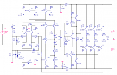
I see your schematic does't have component values. Can you post one that does?
Your board looks really good - have you printed it out full size to check that everything fits? Too many times I go ahead and make the board, only to find that the parts don't fit
What program did you use for the layout? Mind posting or sending me a pdf of the copper and the silkscreen? I could give your design a listen myself.
Member
Joined 2009
Paid Member
Hi,
Excellent question! Well, I have dry fitted most of the parts to a print out although I will repeat that process again shortly because the recent print out was from a printer that I don't trust the scaling. Trouble is, some of the parts are on back order so I have to trust the manufacturers datasheet.
I didn't leave much space for a heatsink on the VAS device did I? Neither did I consider a variable footprint for playing with compensation capacitors. On the other hand, I can make another one.
Now I have to come clean on the pcb design. I downloaded Eagle, the free pcb layout software. It's one that has all the features and I was looking forward to learning the ropes on this. It is limited to small boards, smaller than mine so eventually I'd have to pay for a license or cut the design into two pieces. The real issue is that you have to define parts not in their library and this became laborious quickly. I was too impatient. I used a graphics drawing program (Macromedia Freehand) that I am familiar with and just drew everything, so the files are no use to man nor beast I'm afraid. If anybody has a library for Eagle with the parts set up I would be willing to redraw it - but since it hasn't been proven to work yet this should perhaps wait.
Is there in fact an Eagle library available on this forum that everyone uses and contributes to yet somehow I missed it ?
Still, it's gratifying to see the old hands like yourself show some interest. I'll post some files shortly.
Bigun said:Hi,
Now I have to come clean on the pcb design. I downloaded Eagle, the free pcb layout software. It's one that has all the features and I was looking forward to learning the ropes on this. It is limited to small boards, smaller than mine so eventually I'd have to pay for a license or cut the design into two pieces. The real issue is that you have to define parts not in their library and this became laborious quickly. I was too impatient..
This is classic of free or cheap PCB software packages.
They either limit the pin count and/or you have to design the components yourself.
It takes a massive amount of work to design the millions of possible components and thats why full packages cost so much.
Member
Joined 2009
Paid Member
Member
Joined 2009
Paid Member
nigelwright7557 said:
This is classic of free or cheap PCB software packages.
They either limit the pin count and/or you have to design the components yourself.
It takes a massive amount of work to design the millions of possible components and thats why full packages cost so much.
I will hand it to them though, the library that they include with the free version is pretty extensive - I just couldn't find my parts. If DigiKey were to offer a library linked to their catalogue part numbers then they would have a captive audience....
Member
Joined 2009
Paid Member
Here's the schematic reposted with values. But it's a work in progress...
The values for the TGM version 1 are pretty set. They are based on what I imagine AKSA would be happy with (differences certainly include C11, C13 and bits of the NFB for example). In this version the LTP will be set at a low current with no emitter degeneration. Linearity/accuracy is not the primary aim for me here but to sample the sound with some 2nd order harmonics from the imperfectly matched LTP. With 20V secondaries I figure the supply rails at +/- 26.5V. I also need to check R8/R9 to ensure the gain isn't set too high that I get clipping.
The pcb is designed to allow me to make TGM versions 2 and 3 so the schematic includes parts that I haven't worked out values for yet since they aren't needed for version 1. These are R23 and up and C16.
Attachments
Member
Joined 2009
Paid Member
Bigun said:you can never have too many rectifier diodes...
I prefer these:
An externally hosted image should be here but it was not working when we last tested it.
Compact, high power. Not as glamourous, but get the job done splendidly.
Your outputs layout is a little small for the TO-264 package. Are you planning on the FJP5200/1943? These are TO-220's.
Member
Joined 2009
Paid Member
Yes - are they bad ? - my power requirements are not high (sensitive speakers) I didn't need to get output devices in the large package (e.g. 25W might well destroy my HT speakers and my big speakers would be better bi-amped so I'd still be able to test them out without frying things). I have the Fairchild 5200 devices in TO-220 packages rated at 17A 80W (and their complimentary equivalents). I've no idea if they will be as good as the Toshiba originals.
I (foolishly ?) try to single-source all I need from DigiKey to keep it easy. I specifically wanted soft-recovery rectifiers and I couldn't find them in compact form.
What is the compact bridge rect. you have there ?
The compact bridge would have helped me shrink my layout, because my pcb size is ideally fixed by the width of my heatsink (I have 6 meters of 184mm wide extruded Al) and the height of the box (80mm). But the shrinking is done for now.
Everything is bagged for static protection - I don't remember BJTs being that sensitive.
Bigun said:I (foolishly ?) try to single-source all I need from DigiKey
What is the compact bridge rect. you have there ?
I do the same - Digikey man!
The bridge is from Digikey: GBJ1506
I have a couple of comments on your schematic. First, your front end is running way too cold (talked about before). Second, your input cap is a tad low, might cut off some LF response. Third, your VAS is running a bit hot (definitely need a sink on that).
Look at deleting R3 and adjusting R30 to a lower value (and either use a lower value for P2 or eliminate it altogether).
R25 and R26 in your CFP inputs may be too low. I worked up a similar input and used 1K in that position.
Attachments
- Status
- This old topic is closed. If you want to reopen this topic, contact a moderator using the "Report Post" button.
- Home
- Amplifiers
- Solid State
- TGM Amplifier ?