Member
Joined 2009
Paid Member
Lumba Ogir said:I cannot see why would that happen.
A strong AC component of the output appears at the junction of R5 and R6 via the Bootstrap cap. Some of this produces a current across R5 and results in a signal at the LTP +ve rail. This modulates the current through the LTP. In the base design there is an RC filter on the +Ve rail, made up from R10 and C3. In the case of the bootstrap signal the combination of R5/C3 produces a low pass pass filter that keeps the signal out of the LTP.
Lumba Ogir said:Why are you against degeneration resistors?
I'm not, not one bit. But version one of TGM, my starting point, is essentially an AKSA clone. I want to hear this version first. I've never heard AKSA. I'm making a simple pcb to explore this first. It has no degeneration resistors. I thought it would be interesting to replace the LTP devices on this version with a pair of JFETs - just for interest. There would be no degeneration resistors in that case. I've also no idea what kind of LTP bias current would work best with JFETs or if the output from the LTP can drive the VAS properly in the design if unchanged.
Gareth,
I was rather wondering how all that would give a nice increase of H2? You should not use LTSpice for distortion analysis, it made you come to several wrong conclusions in this thread. I`m sure Andy agrees 100%.
Considering the extremely precarious situation, what about 5mA LTP current?
I was rather wondering how all that would give a nice increase of H2? You should not use LTSpice for distortion analysis, it made you come to several wrong conclusions in this thread. I`m sure Andy agrees 100%.
Considering the extremely precarious situation, what about 5mA LTP current?
Member
Joined 2009
Paid Member
Well I think it boils down to a few things. Perhaps I'll give the long answer here whilst waiting for dinner!
I had two goals when I started this project. First one was to build an amplifier, the 2nd one was to learn. The constraints are mostly time and the fact that knowing myself I will eventually wander off on to some other hobbies of mine if I get bogged down into too many difficulties.
At my work I make choices based on what is in the best interest of the business. At home to get to make choices on my own whim. I decided that I liked three possible approaches, a) a Chip Amp, b) Susan Parker amp, c) discrete SS amp. I crossed off a) because it doesn't give me a chance to learn enough. I haven't crossed off b) yet, but it's too heavy for my first project which is the 5 channel HT amp. That left c). I perused this forum and found a lot of positive comments about AKSA. This design is no longer available but thought I could learn enough to make something similar. This is TGM 1.
Whilst learning about TGM1 I was lead to understand it's weaknesses. I developed the concept for TGM2 and 3. Even these have weaknesses. I have also learned that there is never an end to the process of searching for better performance. But before I go down that road I have to take first steps and this means making TGM1. It's my AKSA clone, or at least my interpretation of what I think AKSA is.
There is some information in the public domain about AKSA. From what I think I have learned, it runs with relatively low LTP current. It may be bad from some technical aspects but it doesn't change the fact that it is the AKSA design. There are many other areas of AKSA that one can be critical about based on a technical argument, but I believe that the 'proof is in the pudding' and this amplifier has been received very well indeed. So I trust that Hugh has good reasons for his approach and I try to learn what they are.
In the meantime I want to produce TGM1 to be as close to AKSA as the information available allows me. And I believe this means an LTP bias current that is relatively low. I may be wrong, maybe AKSA has a different current, but I can always change a resistor !
Do I trust the simulations - well to some extent I do. There is enough consensus that Spice provides good data that I am willing to give it the benefit of doubt. What it can do is help me to see what kind of starting values for components I should use before doing experiments. It allows me to see trends - what things are likely to change in the performance if I make changes to the circuit. This is much easier to do in Spice than on a bread board.
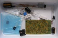
The last package from digikey arrived today. Now I can start to build something.
I had two goals when I started this project. First one was to build an amplifier, the 2nd one was to learn. The constraints are mostly time and the fact that knowing myself I will eventually wander off on to some other hobbies of mine if I get bogged down into too many difficulties.
At my work I make choices based on what is in the best interest of the business. At home to get to make choices on my own whim. I decided that I liked three possible approaches, a) a Chip Amp, b) Susan Parker amp, c) discrete SS amp. I crossed off a) because it doesn't give me a chance to learn enough. I haven't crossed off b) yet, but it's too heavy for my first project which is the 5 channel HT amp. That left c). I perused this forum and found a lot of positive comments about AKSA. This design is no longer available but thought I could learn enough to make something similar. This is TGM 1.
Whilst learning about TGM1 I was lead to understand it's weaknesses. I developed the concept for TGM2 and 3. Even these have weaknesses. I have also learned that there is never an end to the process of searching for better performance. But before I go down that road I have to take first steps and this means making TGM1. It's my AKSA clone, or at least my interpretation of what I think AKSA is.
There is some information in the public domain about AKSA. From what I think I have learned, it runs with relatively low LTP current. It may be bad from some technical aspects but it doesn't change the fact that it is the AKSA design. There are many other areas of AKSA that one can be critical about based on a technical argument, but I believe that the 'proof is in the pudding' and this amplifier has been received very well indeed. So I trust that Hugh has good reasons for his approach and I try to learn what they are.
In the meantime I want to produce TGM1 to be as close to AKSA as the information available allows me. And I believe this means an LTP bias current that is relatively low. I may be wrong, maybe AKSA has a different current, but I can always change a resistor !
Do I trust the simulations - well to some extent I do. There is enough consensus that Spice provides good data that I am willing to give it the benefit of doubt. What it can do is help me to see what kind of starting values for components I should use before doing experiments. It allows me to see trends - what things are likely to change in the performance if I make changes to the circuit. This is much easier to do in Spice than on a bread board.
The last package from digikey arrived today. Now I can start to build something.
Bigun said:In the meantime I want to produce TGM1 to be as close to AKSA as the information available allows me. And I believe this means an LTP bias current that is relatively low. I may be wrong, maybe AKSA has a different current, but I can always change a resistor !
Not really. Without any emitter degeneration you are forced to run a rather low LTP tail current to keep its gm down.
With a tail current boost to 5mA you'd need a silly-high closed loop gain or a 1nF Cdom to stabilise the thing.
Member
Joined 2009
Paid Member
G.Kleinschmidt said:
Not really. Without any emitter degeneration you are forced to run a rather low LTP tail current to keep its gm down.
With a tail current boost to 5mA you'd need a 1nF Cdom to stabilise the thing.
I had been thinking only in terms of the benefits of degeneration for swamping the variability in Re and neglecting the nfb benefit on stability.
But on the positive side, a month ago I wouldn't have had a clue at all !
Gareth,
when biasing (especially plain) transistor stages, power dissipation often is a limiting factor.
When real load is present, the beautiful static measurement data can become academic. Some details discussed previously have importance for the dynamic behavior and are not justly appraised by LTSpice.
when biasing (especially plain) transistor stages, power dissipation often is a limiting factor.
When real load is present, the beautiful static measurement data can become academic. Some details discussed previously have importance for the dynamic behavior and are not justly appraised by LTSpice.
Lumba Ogir said:Some details discussed previously have importance for the dynamic behavior and are not justly appraised by LTSpice.
You have no idea WTF you're talking about.
Member
Joined 2009
Paid Member
Hi Andy. An academic friend of mine who specialises in linear regulator psychoacoustics says that Lumbar is quite correct and scientifically astute. You are being elitist and narrow-minded.
Bigun,
The best thing you could do here is learn all about bode plots and learn how to simulate these simple amplifier topologies in LTspice with the loop gain probe. Then you can change things like Cdom, the LTP degeneration, closed loop gain, etc and see exactly how interact and impact on the amplifiers performance and phase margin.
Disclaimer: just BS'ing in that 1st paragraph.
That is good advice for phase 1, to get one up and working ,stable.. to fine tune the sound by trial and error.Then you can change things like Cdom, the LTP degeneration, closed loop gain, etc and see exactly how interact and impact on the amplifiers performance and phase margin.
But keep your other foot in the "real world" camp. There are
many subtle aspects of amplifier design that can only be
experienced by "cranking it up" (with scope and DVM in hand).
I would not build your amp exactly as you have it , but I would not tell you not to build it your way... either. This is for you to
learn , trial and error.. the best teacher. If you were about to
electrocute yourself, that is different.

keep up the good work and keep an open mind, BG. You appear to be a much better student than I was in the beginning.
")
OS
Member
Joined 2009
Paid Member
I did electrocute myself once. Many years ago when I was living in the UK a friend of mine found an old Heathkit radio at a junk sale that included a transmitter. First and only time I've felt 240V AC. My friend couldn't stop laughing - "should have seen the look on your face !" was all he had to say about it
I did go back and look at Spice to see what impact there was in changing the bias current on the drivers (as Carlos had suggested). Even with 180R I had just over 12mA. I increased this upto 220R to drop the current. No impact on distortion characteristics. Hugh says "On the AKSA I use 5.5mA, 8mA for two output pairs...the resistor will typically be around 220R for a single pair".
I still need to drill the pcb and think about how to go about matching transistors and how closely they need to be matched. I have started to kit the parts...
Attachments
Member
Joined 2009
Paid Member
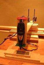
BiGun-maybe this will give you and everyone else a laugh, here's my pcb drilling set up.
I like that drill rig.. I must make one for myself.
I did go back and look at Spice to see what impact there was in changing the bias current on the drivers (as Carlos had suggested). Even with 180R I had just over 12mA. I increased this upto 220R to drop the current. No impact on distortion characteristics. Hugh says "On the AKSA I use 5.5mA, 8mA for two output pairs...the resistor will typically be around 220R for a single pair".
In this aspect of the EF I have seen wide variations of opinion. Your 4-5ma is the lowest I have seen all the way to RMI/abomination (roender/MJL) recommending 100ma !
I think this is dependant on device. By simulating my mje15032/33 pair with 2 .step commands (1 for driver R, 1 for vbias R) ,22-25ma gave me lowest thd20 by just a tiny margin (10-20ppm). The 2sc/sa drivers "bottomed out" at 10-12ma.
I did notice that THD stayed rather low across a wide range
of current (5-50ma).
In real life , the sound remains the same.. provided you keep OPS
bias constant. Thermally , even 20+ma stays just warm with PCB mounted heatsinks even after an extended "jam session".
OS
PS. I got a 400v shock right in my mouth after stripping a live
wire on a tube amp plate supply with my teeth. When I woke up , I was IN a hole in the wall and my ears were still ringing. I did this at the age of 17. 25 years later I have only been shocked another 2-3 times , but never for long (very "gunshy" now).
Bigun said:here's my pcb drilling set up.
Cool jig! I free hand myself (hey, that sounds dirty
)...ostripper said:
...stripping a live wire on a tube amp plate supply with my teeth.
I use(d) that method myself. Opened beer bottle, etc.
Still the best stripper for small wires.
Member
Joined 2009
Paid Member
ostripper said:PS. I got a 400v shock right in my mouth after stripping a live
wire on a tube amp plate supply with my teeth
Hell's Teeth OS, I never heard anyone putting a live wire in their gob. That must have been really nasty.
edit: I gave up using my teeth for this as a kid when I got a batch of nylon/PTFE coated wire which was a pig to strip.
trial and error.. the best teacher
I have bought 25 pairs of output devices just in case it proves to be a real trial and lots of error
Lumba said:...there`s nothing wrong with it.
Thanks ! - have now finished the drilling, tried each part in it's place, everything lines up. This was also the first pcb in which the toner transfer simply worked first time around (instead of making me want to throw it all out the window). It's a good omen.
- Status
- This old topic is closed. If you want to reopen this topic, contact a moderator using the "Report Post" button.
- Home
- Amplifiers
- Solid State
- TGM Amplifier ?