Member
Joined 2009
Paid Member

Hi Gareth, welcome back! Here's my two cents worth:
Push those screw holes right to the edges of the boards and see if you can get the AC and GND connectors to the cap centre line
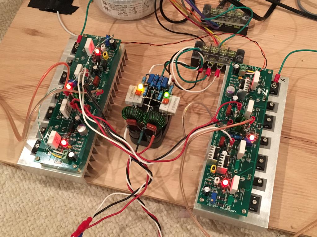
Are those R's in the middle of the bank part of a CRC network? I like to leave a lot of air gap around them because when heavy currents are drawn these can get HOT and when they do you can be sure the caps aren't enjoying the heat.
Personally I like the positive terminals on the 'lytics to all point in the one direction but the way you've done it looks kinda neat too.
Do you really need two charge indicator LEDS on each board?
You really want fuses to each secondary in case a diode fails closed. Why not install the fuse clips onboard to reduce wiring clutter?
How are you going to protect your amp modules and speakers in the event all that stored charge gets dumped into your output transistors and voice coil?
Edit; if you haven't already done so, add some pins in for a snubber across each transformer secondary. I've found that these can be VERY effective in reducing noise caused by certain transformer/diode/wiring combinations. Experimentation is in order; however, I've found 330R and 22n is a good starting point. In fact I've found these to be so beneficial I hardly bother with fancy diodes or CRC networks anymore.
Push those screw holes right to the edges of the boards and see if you can get the AC and GND connectors to the cap centre line
Are those R's in the middle of the bank part of a CRC network? I like to leave a lot of air gap around them because when heavy currents are drawn these can get HOT and when they do you can be sure the caps aren't enjoying the heat.
Personally I like the positive terminals on the 'lytics to all point in the one direction but the way you've done it looks kinda neat too.
Do you really need two charge indicator LEDS on each board?
You really want fuses to each secondary in case a diode fails closed. Why not install the fuse clips onboard to reduce wiring clutter?
How are you going to protect your amp modules and speakers in the event all that stored charge gets dumped into your output transistors and voice coil?
Edit; if you haven't already done so, add some pins in for a snubber across each transformer secondary. I've found that these can be VERY effective in reducing noise caused by certain transformer/diode/wiring combinations. Experimentation is in order; however, I've found 330R and 22n is a good starting point. In fact I've found these to be so beneficial I hardly bother with fancy diodes or CRC networks anymore.
Last edited:
Member
Joined 2009
Paid Member
Hi Chritian,
I'm quite tight on space, this board is 10cm x 10cm and I'm struggling to keep the working devices within an area that my Freeware Eagle layout software will be happy with.
You are correct, the main annoyance is positioning of the resistors in the CRC network. I'll give this some additional thought - perhaps they can go under the board.
The LEDs act, in series with their current limiting series resistors, as bleeders for the caps so they have a dual purpose but the individual LEDs could be replaced with wire links if one didn't want them there.
I've never fused a transformer secondary, I've always limited myself to rail fuses after the rectifiers. Do rectifier diodes fail short easily ? I've never seen it happen and I've never seen commercial equipment use them. What's you take on the risk ?
Protection ? - if the amplifier output gets shorted then it's going to suffer from high current flow, no two ways about it. What else would cause all that stored charge to flow other than the music ?
That's a good point, I will revisit the gain structure once I have the board designs finished - some tweaking of parts values may be in oder here.
I'm quite tight on space, this board is 10cm x 10cm and I'm struggling to keep the working devices within an area that my Freeware Eagle layout software will be happy with.
You are correct, the main annoyance is positioning of the resistors in the CRC network. I'll give this some additional thought - perhaps they can go under the board.
The LEDs act, in series with their current limiting series resistors, as bleeders for the caps so they have a dual purpose but the individual LEDs could be replaced with wire links if one didn't want them there.
I've never fused a transformer secondary, I've always limited myself to rail fuses after the rectifiers. Do rectifier diodes fail short easily ? I've never seen it happen and I've never seen commercial equipment use them. What's you take on the risk ?
Protection ? - if the amplifier output gets shorted then it's going to suffer from high current flow, no two ways about it. What else would cause all that stored charge to flow other than the music ?
I see +5dB for the voltage amp, -0.5dB for the Buffer and +31dB for the Power amp.
Those three stages come to +35.5dB.
I usually use +27dB to +29dB for my gain stages and find that is too much.
I have seriously considered looking at re-doing the stability/gain of all my Power Amplifiers to try to get the gain down to +20dB, or even a bit below that. Not bitten that bullet yet.
Do you really need all that gain to throw away in the attenuator?
That's a good point, I will revisit the gain structure once I have the board designs finished - some tweaking of parts values may be in oder here.
Hmm 10x10 is not a lot for a dual mono board. Have you considered laying this out as a true mono board to give yourself a little extra space and installing two boards inside the case?
Aesthetically I don't like four indicator leds when two would suffice. Just my preference. We can be sure that by the time the led in series with the drain resistor on the +ve rail has dimmed, the -ve rail with just the resistor will have also drained that bank to a trivial value too. But a led per channel is a good idea since each could be powered from its own transformer, etc.
I used to think the same as you about fusing the transformer secondaries. But I did have a diode blow (possible user error!) causing the traffo to make horrible sounds before the primary fuse blew. Fortunately in this case it was a close rated / fast acting type because it had an inrush limiting circuit, so this might have resulted in a blown transformer had the mains fuse been the usual high amperage slow blow type. Now I fuse all windings on the transformer and use microprocessor controlled low Rds(on) Mosfets to switch off the main rails in the event of DC on speaker line, etc.
I'm not recommending you should do same - just giving you a perspective.
A close rated fuse will blow almost instantly if the output @ the secondary suffers a shorted rectifier.......................
I've never fused a transformer secondary, I've always limited myself to rail fuses after the rectifiers. Do rectifier diodes fail short easily ? I've never seen it happen and I've never seen commercial equipment use them. What's you take on the risk ?
Protection ? - if the amplifier output gets shorted then it's going to suffer from high current flow, no two ways about it. What else would cause all that stored charge to flow other than the music ?...............
It's the practice of using enormously rated primary fuses that puts the transformer at risk.
Member
Joined 2009
Paid Member
I agree with Andrew, I think I'll leave it fused on the primary side - although without using a slow-turn on module one has to rate the fuses large enough to survive the inrush of the transformer and herein lies the tradeoff. Of course, after I've had my transformer blow up I'll then have to be less cavalier !
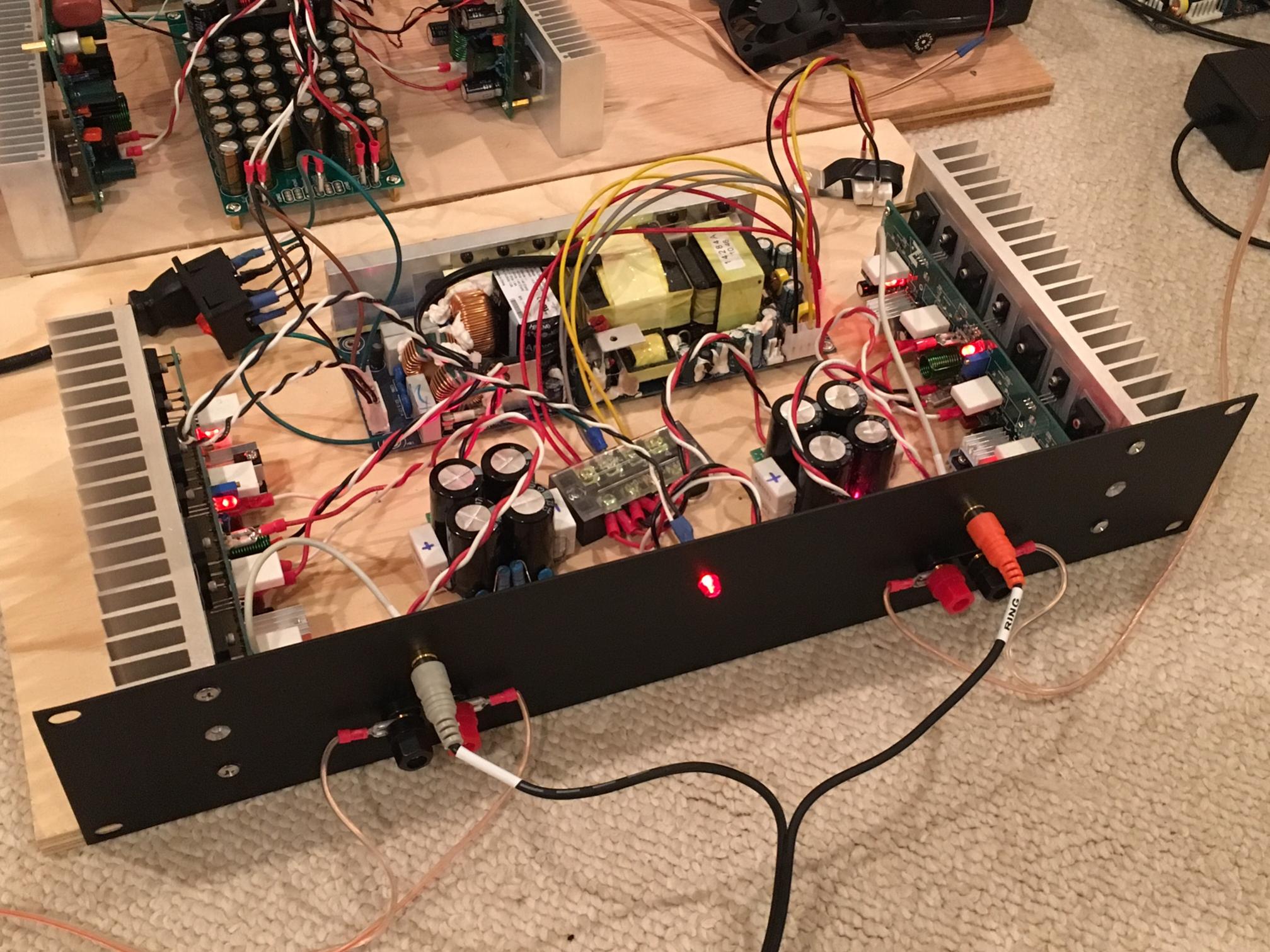
I can't make the PSU board any larger, my chasis is pre-chosen and there's very little space. It's about half the size of Xrk's chasis (looks great by the way) although a bit taller - In fact, the PSU board will have to sit atop the power transformer toroid as the only place left to put it and so the mounting holes need to stradle the donut underneath. But out-board resistors could be a good option - I'll see if I can't provide options on the pcb so that one way or another I end up with something workable.
I'm setting myself the goal of taping-out the pcb designs to the board house this week, one way or another.
Last edited:
On my VHEX, the SMPS has a 5A slow-blow fuse per rail (at 53v), and I fuse the input to the SMPS to allow full capacity of SMPS at 120vac input for 450w continuous rating or 4A. On toroidal transformers, having fuses on primary is good to protect trafo, and after PSU cap bank is good to protect amp from overload or short circuits.
It is nearly impossible to protect an abused amplifier using fuse/s.On my VHEX, the SMPS has a 5A slow-blow fuse per rail (at 53v), and I fuse the input to the SMPS to allow full capacity of SMPS at 120vac input for 450w continuous rating or 4A. On toroidal transformers, having fuses on primary is good to protect trafo, and after PSU cap bank is good to protect amp from overload or short circuits.
They are too slow, the damage to the semiconductors is already done.
Fuses are very good at preventing overloaded copper from setting fire to the insulation/curtains/carpets/floorboards. Fuses are not good for protecting transistors.
It is nearly impossible to protect an abused amplifier using fuse/s.
They are too slow, the damage to the semiconductors is already done.
Fuses are very good at preventing overloaded copper from setting fire to the insulation/curtains/carpets/floorboards. Fuses are not good for protecting transistors.
Good point, luckily the output current max on IRFP240/9240's is pretty high and I have yet to burn one out. Although I have blown fuses before on accidental shorts (perforated silicone insulator pads on OPS - caused direct short between +ve and -ve rail. It fried the driver transistors (BD139/140) though.
Vzaichenko's solid-state MOSFET based protection circuit though, I believe is indeed fast enough to save the amp from damage - from what I have been told as anecdotal evidence.
Member
Joined 2009
Paid Member
Member
Joined 2009
Paid Member
OK - I have moved the CRC resistors out of the little hollows between the capacitors. They are still near the capacitors but now easier to access - definitely more sensible.
I ensured that the RC snubbers are across the transformer secondaries too (Ranchu - agree very much with your suggestion on this item). I wonder if the LED + R's across the rails also act like RC networks - diodes are often used as psuedo capacitors on the cathodes of small signal triodes.
Dual Mono Grounding - since the 'grounds' of both channels must connect to the safety earth through disconnecting-diode networks the two 'grounds' will be able to 'see' each other through a couple of diodes. It doesn't seem to be a requirement that I use two separate power transformers - using one transformer with separate bridge rectifiers also keeps the two channel 'grounds' separated by a couple of diodes. Given space constraints two transformers maybe impossible.
A bit of mortality in our amplifiers helps generate a reason to keep building")
This could become Diyaudio's motto!

Member
Joined 2009
Paid Member
Member
Joined 2009
Paid Member
I ordered the volume pot today.
Still waiting to hear from Avel Lindberg on the power trafo.
The BOM is coming along, slowly...
Hugh has matched some power output transistors for me from his private stock - he'll probably shoot me for mentioning it here since this is NOT a public service but since a good deed deserves some credit .... hence this build will use original AKSA parts
Attachments

Last edited:
Gareth,
I have included in your package a couple of AKSA 55 new boards for you, too, so you will actually have an original AKSA 55 with the Rev 2 pcb that I released in 2002........
Enjoy the 'new' AKSA 55! The latest, about to release in a couple of weeks when I have the new badge, is the Super AKSA, using all the tricks over the last 15 years but designed around the original. It uses 42V rails, delivers 85W, uses complementary 280W mosfets, and boasts one of the best harmonic profiles I have ever achieved. It really is a beauty, but then, the original was too!
Cheers,
Hugh
Gareth,
I have included in your package a couple of AKSA 55 new boards for you, too, so you will actually have an original AKSA 55 with the Rev 2 pcb that I released in 2002........
Enjoy the 'new' AKSA 55! The latest, about to release in a couple of weeks when I have the new badge, is the Super AKSA, using all the tricks over the last 15 years but designed around the original. It uses 42V rails, delivers 85W, uses complementary 280W mosfets, and boasts one of the best harmonic profiles I have ever achieved. It really is a beauty, but then, the original was too!
Cheers,
Hugh
Hugh,
So you are back to VFA now.
Cheers
Damir
Damir,
I go where I can get good sound; I am not particularly fixed on one system. In fact the Maya uses VFA too! I have set up an interesting compensation on the SAKSA which is not used much; lag shunt to ground, and phase lead to the fb node. I found that it sounded better than the usual lag comp I use, and in fact I find the compensation more influences the sound quality than the topology... but I might be quite wrong after all. I am a pragmatist!
Hugh
Last edited:
- Status
- This old topic is closed. If you want to reopen this topic, contact a moderator using the "Report Post" button.
- Home
- Amplifiers
- Solid State
- TGM 1i - an integrated hybrid amp inspired by Hugh Dean