LineSource said:I keep watching for a digital amp that can drive about 20 watts into a 0.15 ohm resistive load. A higher frequency chip lkike the TAS5261 would seem valuable as it would reduce the inductor size. IS THIS CORRECT?
If you don't need high fidelity you could make your own fairly easily because you don't need much voltage at all to reach 20W into a 0.15ohm load. There are tons of mosfets that have very high current and low voltage ratings. You will need a rather beefy low voltage supply though. Probably something robust enough to deliver 15-20A continuous with an output voltage of 5V or less.
Higher switching frequencies allow you to use lower valued inductors. Inductor size is largely determined by inductance value and current carrying capability. You need low winding resistance to carry higher currents and this means larger gauge windings and larger physical size.
-_nando-_ said:May I suggest to we make our own 5261 amp design?
That's the idea
") The output stage is all but designed though. It's the front end design that needs to be tackled.
The output stage is all but designed though. It's the front end design that needs to be tackled.
BWRX said:
If you don't need high fidelity you could make your own fairly easily because you don't need much voltage at all to reach 20W into a 0.15ohm load. There are tons of mosfets that have very high current and low voltage ratings. You will need a rather beefy low voltage supply though. Probably something robust enough to deliver 15-20A continuous with an output voltage of 5V or less.
Higher switching frequencies allow you to use lower valued inductors. Inductor size is largely determined by inductance value and current carrying capability. You need low winding resistance to carry higher currents and this means larger gauge windings and larger physical size.
VERY high fidelity is required into this 0.15 ohm super detailed ribbon speaker. Is a robust 5V PI filter adequate, or is a solid state regulated power supply necessary?
Any equations for calculating the LC filter required for a 0.15 ohm speaker at about 20 watts? Any suggestions for output MOSFET? I was thinking that a few MOSFETS and LC filters in parallel would be required for this application. Anyone try a design like this?
Attachments
LineSource!
Why don't you use a transformer? 500Hz...100 kHz transfer is not hard to achieve.
The problem is not size of inductor. It can be 10*10*10 mm. (OK, current is high, but inductance is very low!) The problem is resistance of switching MOSFETs. They should be less then 0,03 ohm.
BWRX!
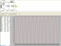
Yes. Simplified: 1 kHz is present in order to show that low noise is achieved not by turning off output devices, but because of very small jitter, etc...
Why don't you use a transformer? 500Hz...100 kHz transfer is not hard to achieve.
The problem is not size of inductor. It can be 10*10*10 mm. (OK, current is high, but inductance is very low!) The problem is resistance of switching MOSFETs. They should be less then 0,03 ohm.
BWRX!
Does that even make any sense to publish graphs using such low levels?
Yes. Simplified: 1 kHz is present in order to show that low noise is achieved not by turning off output devices, but because of very small jitter, etc...
I would opt not to use a TI front end at all.-_nando-_ said:So, what ADC ? PCM3002 is a 48Khz of sample rate, stereo. ADCs with more sample rate should sound better or 48Khz is more than enough? Suggestions ?
Still, they could just say so... Or even better, publish noise graphs using more realisitic input levels. It would be nice to see THD at 1W or more with various inputs (1kHz, 19 and 20kHz, etc.).Pafi said:Yes. Simplified: 1 kHz is present in order to show that low noise is achieved not by turning off output devices, but because of very small jitter, etc...
Re: which then?
I was thinking of leaving the options open so that it would be possible to use a front end that is discrete, comparator based, or chip based. The discrete and comparator based front ends combined with post filter feedback could make the amp self oscillating, but I forgot that the outputs will be floating at half the supply voltage...
It's probably possible to use split supplies with this chip so that the ouputs would be floating at ground potential. It would just require a 12V supply referenced to the negative rail for the internal circuitry. I was also thinking that this chip could be used as two single ended outputs instead of just a bridged output stage. The input, output, and power connections show that each output stage is basically completely separate from the other. Plus, they show completely separate internal blocks for each half bridge as well. Instead of 120W x 1ch it would be really nice to have 50W x 2ch.
Would you guys rather use a TI solution for the front end?
FastEddy said:Got something else in mind? (I'm not married to the TI chip either.)
-_nando-_ said:Why not TI ? Are you thinking in something else to the TAS5012?
I was thinking of leaving the options open so that it would be possible to use a front end that is discrete, comparator based, or chip based. The discrete and comparator based front ends combined with post filter feedback could make the amp self oscillating, but I forgot that the outputs will be floating at half the supply voltage...
It's probably possible to use split supplies with this chip so that the ouputs would be floating at ground potential. It would just require a 12V supply referenced to the negative rail for the internal circuitry. I was also thinking that this chip could be used as two single ended outputs instead of just a bridged output stage. The input, output, and power connections show that each output stage is basically completely separate from the other. Plus, they show completely separate internal blocks for each half bridge as well. Instead of 120W x 1ch it would be really nice to have 50W x 2ch.
Would you guys rather use a TI solution for the front end?
How about we start at ground level, a basic mono output module with a simple PWM input circuit, then once we have something up and running then we can discuss how to improve it, but if all you want is a sub amp, say, the basic circuit will do the job. Once we have that up and running collectively in front of us, then we can measure, listen and adapt for best performance to come up with a better implementation.
My comments on the various front ends basically implied that you'd have a separate front end board that would connect to the TAS5261 output board by wires or jumpers.
I've already begun laying out a board in eagle but I would love to see what you come up with too Al.
Al - did you ever reply to my email? If you did, I have not received it. I checked my spam filter to make sure.
I've already begun laying out a board in eagle but I would love to see what you come up with too Al.
Al - did you ever reply to my email? If you did, I have not received it. I checked my spam filter to make sure.
Re: Re: which then?
That would be nice!
I just ordered some samples also and interested if somebody could come out with an easy board to solder up.
Solve
BWRX said:
Instead of 120W x 1ch it would be really nice to have 50W x 2ch.
That would be nice!
I just ordered some samples also and interested if somebody could come out with an easy board to solder up.
Solve
BWRX said:My comments on the various front ends basically implied that you'd have a separate front end board that would connect to the TAS5261 output board by wires or jumpers.
OK, fair enough, though I think it would be nice to have a basic PWM stage on board for those that just want a simple amp.
I've already begun laying out a board in eagle but I would love to see what you come up with too Al.
Haven't had time as yet. Can someone point me to a source for the required output inductors so I can use an appropriate footprint, it would be nice to get a part that everyone can easily get hold of.
Al - did you ever reply to my email? If you did, I have not received it. I checked my spam filter to make sure.
Did, but I'll do it again!
pinkmouse said:I think it would be nice to have a basic PWM stage on board for those that just want a simple amp.
It certainly would be. The problem with the TI front end is that it isn't terribly simple but it is the best match because it was designed to work with their output stages. Upon further consideration though, it does look to be one of the easier ones to implement.
I also received and replied to this last email you sent. Thanks!
Do we go for TAS5518 PWM controller + 2xTAS5261?
TAS5518 can control 8 channels, that is too much, or not. In any case it has best characteristics among other TI PWM controllers.
Attached are the schematics, from TI.
http://www-s.ti.com/sc/psheets/slaa332/slaa332.pdf
TAS5518 can control 8 channels, that is too much, or not. In any case it has best characteristics among other TI PWM controllers.
Attached are the schematics, from TI.
http://www-s.ti.com/sc/psheets/slaa332/slaa332.pdf
Attachments
How about that. Sometimes you get so busy looking at specs that you forget the important things like whether or not it uses an analog input! Good catch there Al.
What we could do is use one of their low power filterless class d solutions to derive the PWM signal for the TAS5261.
Something like the TPA2000D1 accepts an analog input, works off of 5V, and provides both non-inverted and inverted PWM outputs. It should work really well driving something as easy as the inputs of the TAS5261.
pinkmouse said:I may be being particularly dense, but I can't see any analogue inputs on that chip.
These are part of the Equibit (ie PurePath) line. Pure digital parts - no analog inputs. It's the tech use in the Tact amps and the Panasonic XR series receivers. For conventional analog-input applications I'd guess that a Tripath or UcD would be a better bet.
With the 8 channel evm going for $400, not a bad deal. I have a Delta 1010 soundcard that has 8 channels of I2S output on a DB25 which would be a perfect match, although I still haven't gotten around to reverse-engineering the pinout.
- Status
- This old topic is closed. If you want to reopen this topic, contact a moderator using the "Report Post" button.
- Home
- Amplifiers
- Class D
- Texas Instruments TAS5261