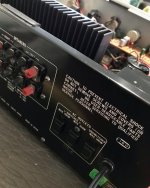
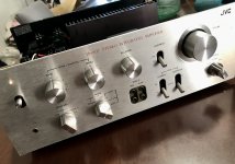
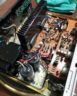
Please don´t use the "-" sign as separator, it gets confused with the "-" used as "minus" sign.Hi guys I know is a very old thread but hey, has relevant information. I got a vintage JVC amp and I been troubleshooting the thing, someone had been in there before so i found several thing loose and some destroyed resistors. Then I found a couple of bad transistors checked diodes and replaced some caps, because the thing was half apart anyway, But I'm going around , finally got to the stk0040, someone had one out already, trying to get some information on them, i got here. I did the resistance check, then diode tes(short) and finally a voltage check(again).
P1-0
P2--37.7
P3-37.6
P4-0
P5-0
P6-0
P7-0
P8--.06
P-9-37.7
P10-37.7
so if I understand it correctly the thing is toast!!, thanks in advance for your help.
If anything,leave 2 or 3 blank consecutive spaces.
So:
No P2--37.7 but:
P2 -37.7
Also mention units used, so:
P2 -37.7V
the less we have to guess, the better we focus on the actual problem
")
Hi Junm,I just converted mine (STK0050) output to a Mosfet IRFP240/IRFP9240 pair with 6.8v Zener on Bias and it works for my SX-780. This chips are Hard to find now and most of the available on online stores are Fakes or relabelled. Darlington pair output can also be used but adjust the bias zener diode value or provide a suitable VbE spreader.
Could you please post a simple diagram for this circuit ?
Thanks
Hi guys, Just to keep this going, after replacing the stk-0040 and a Fet, 1 transistor and two resistors the JVC is humming again. Now cleaned is set aside for a full restoration, next year. Noe time to figure out what's wrong with the STR V6, RH channel (short)