Hi all
Some days ago I bought some 13E1 tubes under the condition that I could test them and in case they were bad I could return them. I do not think they are bad, as they are in white boxes marked which tube they contain (so, no generic white box), and according to the seller, came straight from the Dutch army (code 5960). There are not any spots or whatever on them.
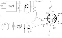
So I want to test them. I set up a test jig, as shown on the picture. My idea is to heat the valves, apply a voltage of -60V on the grid, and slowly, with a Variac, rise the B+ voltage up to about 300V, where, according to the datasheet, the tube should be drawing 200mA.
Today I concluded the test jig, fit in the first 13E1, let it heat up for 30 minutes, and then slowly started to increase the B+. When I arrived at about 180VDC, there was no current flowing, but then, suddenly, things started to go fast with 200V on the plate and -60VDC bias I was getting about 1.5VDC across the 3.9R resistor in the cathode, which corresponds to about 400mA being drawn through the tube. Well, I expected the tube to draw some current, but that much... the tube also made a 'purple' flash... I did not give up
  I:
I:
- increased bias (turned it more negative)
- current drawn went down
- increased B+
- current drawn went up
- increased bias (turned it more negative)
- current went down..
and so until arriving at -90VDC. But at this point the B+ was maybe at about 280VDC, with 400mA flowing. I was surprised that really small changes in B+ have such influence on current drawn: I know this is common for a tube like 13E1, just like it is for a 6AS7 or 6C33C, but so much... still lots of things to learn.
So, what I ask you is to give a look at the picture, comment on the procedure, etc, as I believe tere is a serious mistake somewhere, and I do not want to lose any 13E1 (although I am sure they can stand some abuse, maybe I am to abusive with them). In the evening I will do my homework, checking the whole circuit again
As to the pin 6: it is the heaters CT, I thought it would form a nice 'star ground', and now the heaters aren't floating anymore. I do not see any problem with it for those test purposes, but if you say: that is complete BS you did there, I will change it.
The HV trafo has an ouput of 330VAC (for 220VAC in), but with the variac any voltage can be selected. The capacitor is a really large 100muF/750VDC MKP.
I thank you all for your patience and time!
Erik de Best
Some days ago I bought some 13E1 tubes under the condition that I could test them and in case they were bad I could return them. I do not think they are bad, as they are in white boxes marked which tube they contain (so, no generic white box), and according to the seller, came straight from the Dutch army (code 5960). There are not any spots or whatever on them.
So I want to test them. I set up a test jig, as shown on the picture. My idea is to heat the valves, apply a voltage of -60V on the grid, and slowly, with a Variac, rise the B+ voltage up to about 300V, where, according to the datasheet, the tube should be drawing 200mA.
Today I concluded the test jig, fit in the first 13E1, let it heat up for 30 minutes, and then slowly started to increase the B+. When I arrived at about 180VDC, there was no current flowing, but then, suddenly, things started to go fast
with 200V on the plate and -60VDC bias I was getting about 1.5VDC across the 3.9R resistor in the cathode, which corresponds to about 400mA being drawn through the tube. Well, I expected the tube to draw some current, but that much... the tube also made a 'purple' flash... I did not give up I: - increased bias (turned it more negative)
- current drawn went down
- increased B+
- current drawn went up
- increased bias (turned it more negative)
- current went down..
and so until arriving at -90VDC. But at this point the B+ was maybe at about 280VDC, with 400mA flowing. I was surprised that really small changes in B+ have such influence on current drawn: I know this is common for a tube like 13E1, just like it is for a 6AS7 or 6C33C, but so much... still lots of things to learn.
So, what I ask you is to give a look at the picture, comment on the procedure, etc, as I believe tere is a serious mistake somewhere, and I do not want to lose any 13E1 (although I am sure they can stand some abuse, maybe I am to abusive with them). In the evening I will do my homework, checking the whole circuit again
As to the pin 6: it is the heaters CT, I thought it would form a nice 'star ground', and now the heaters aren't floating anymore. I do not see any problem with it for those test purposes, but if you say: that is complete BS you did there, I will change it.
The HV trafo has an ouput of 330VAC (for 220VAC in), but with the variac any voltage can be selected. The capacitor is a really large 100muF/750VDC MKP.
I thank you all for your patience and time!
Erik de Best
Attachments
Just a guess, but could it be that it's breaking into oscillation? Try it with a 1k stopper, the 100k feed resistor from the bias dropped to 20k, and a small cap (like 0u01) connected from grid to cathode, along with the local bypassing of the plate which you've already done.
I think the connections are right, but your numbering isn't.
I think the connections are right, but your numbering isn't.
Hi Stuart
Many thanks for replying. I tested your recommendation, but still got weird results. At the end, when I turned down the Variac, I observed that voltage on the cap decreased very slowly...I measured the time, with and without tune connected, and they were the same. Well, tube was not even drawing current... but I fried three resistors (the 3R9 ones, they measured in the M ohm range afterwards).
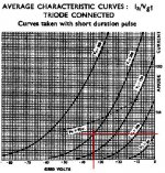
then I disconnected everything, got a (measured) 98R resistor and put it from cathode to ground, and a 1k resistor from grid to ground. Warmed the valve, and applied B+ until reaching 200V across (anode to cathode) the valve. This happened at 227V. Cathode at 27V, with a 98R resistor = 275mA being drawn. Looking at the curves in MJ's book it seems that one would need less than 200VDC to get this current flowing, that is, the tube should be weak. On the net I found another set of curves, but for short duration pulses. I draw the 270mA line, and where it crosses the 200VDC line it reads that the grid should be at about -35V. My conclusion, again, is that the tube is weak, but I do not know if it applies here. Any comment on this procedure and results is more than welcome.
The first tube I tested, which was the same as the one from the whole procedure from yesterday, had a blue glow between anode and cathode. So I had to check on that also, but seems to be fine. Two other units I tested until now do not show this behavior. I still have some to test!
About the numbering, I have seen that there are differences in numbering of the pins. Duncanamps calls the thick pin number 1
http://tdsl.duncanamps.com/show.php?des=13E1 while on the 13E1 datasheet (also from duncanamps) it is called number 4. I checked and rechecked things about 5 times, but with the results of today I know that at least the connections are right.
Many thanks for replying. I tested your recommendation, but still got weird results. At the end, when I turned down the Variac, I observed that voltage on the cap decreased very slowly...I measured the time, with and without tune connected, and they were the same. Well, tube was not even drawing current... but I fried three resistors (the 3R9 ones, they measured in the M ohm range afterwards).
then I disconnected everything, got a (measured) 98R resistor and put it from cathode to ground, and a 1k resistor from grid to ground. Warmed the valve, and applied B+ until reaching 200V across (anode to cathode) the valve. This happened at 227V. Cathode at 27V, with a 98R resistor = 275mA being drawn. Looking at the curves in MJ's book it seems that one would need less than 200VDC to get this current flowing, that is, the tube should be weak. On the net I found another set of curves, but for short duration pulses. I draw the 270mA line, and where it crosses the 200VDC line it reads that the grid should be at about -35V. My conclusion, again, is that the tube is weak, but I do not know if it applies here. Any comment on this procedure and results is more than welcome.
The first tube I tested, which was the same as the one from the whole procedure from yesterday, had a blue glow between anode and cathode. So I had to check on that also, but seems to be fine. Two other units I tested until now do not show this behavior. I still have some to test!
About the numbering, I have seen that there are differences in numbering of the pins. Duncanamps calls the thick pin number 1
http://tdsl.duncanamps.com/show.php?des=13E1 while on the 13E1 datasheet (also from duncanamps) it is called number 4. I checked and rechecked things about 5 times, but with the results of today I know that at least the connections are right.
Attachments
Blue glow between anode and cathode might be gas- it would be interesting to check grid current. Also, I saw that Morgan Jones had found at least one with a cathode-heater hot spot (therre's a picture of it in one of his books), so I'd keep an eye open for that defect.
It looks like the second tube you tested is close to normal. The differences you're seeing are well within what I'd expect for production spreads. Let's see how the rest of the bunch test out.
It looks like the second tube you tested is close to normal. The differences you're seeing are well within what I'd expect for production spreads. Let's see how the rest of the bunch test out.
Hi Stuart
I tested some more units, always putting 200VDC across the tube, and the results are pretty much the same.
I more than fast went to test the offender, and it's grid is really dragging current, value is 'proportional' to the B+, that is, as I increased B+, current drawn went up to. At about 230VDC it was about 0.6mA (600mV across 1k GS). I still have some to measure, and I will therefore put my last DVM across the grid stopper, to check if those drag current to. I do not expect so, but, let's see.
I also looked for hot spots when I warmed the tubes up for half an hour, as recommended by MJ. Haven't seen one hotspot until now!
Erik
Hi Stuart
Can grid current be caused by 'misbehaviour' to the tube, I mean, some thing I did wrong with the former test jig? Sure I can blow up a tube, but this unit is still conducing according to the specs, just that it is pulling some current is not right...
Anyway, you are right, it is a bargain. And, just to make you hate me more, Friday I am going to the same guy to buy the 12 pieces left. The tubes were announced at a 'local ebay', but the seller just received one reaction, and that was mine.
Many thanks for helping me out
Erik
I came across the following septar sockets at ePay. Shall they work better than (NOS) russian sockets? I still need good sockets for the +100W dissipation of the 13E1 tubes.
http://cgi.ebay.com/7-Pin-Septar-Te...ryZ73375QQssPageNameZWDVWQQrdZ1QQcmdZViewItem
Thanks, Erik
http://cgi.ebay.com/7-Pin-Septar-Te...ryZ73375QQssPageNameZWDVWQQrdZ1QQcmdZViewItem
Thanks, Erik
Hello.
I did quite a lot of work with 13E1; in 2001 I built a p-p triode-strapped amplifier.
My first tests were done with an AVO163 valve tester for which I made a simple adaptor. The AVO is limited to 400V and 100mA.
I found that a few of the 13E1s I had were gassy. I was not surprised, 13E1 being a big valve and with a glass base. Often as I neared 90mA the safety device in the 163 would trip. I found that after running the valve for a while this would improve and the "blue" would gradually go. Grid current might be a problem in an amplifier; Morgan Jones's approach using a DC-coupled cathode follower is a good solution to this; also of course with 13E1's high gm, Miller capacitance should also be considered.
II have attached some curves I made at the time:
Later, I build a dedicated test rig, to see if I could push the limits. At the time I was looking into triode-strapping and wondering how far one could go above the g2 limit. I ran a 13E1 triode strapped at 500V and 200mA for a while on test. There were no red anodes, or flashovers.
And the fat pin is No 4
7N7
I did quite a lot of work with 13E1; in 2001 I built a p-p triode-strapped amplifier.
My first tests were done with an AVO163 valve tester for which I made a simple adaptor. The AVO is limited to 400V and 100mA.
I found that a few of the 13E1s I had were gassy. I was not surprised, 13E1 being a big valve and with a glass base. Often as I neared 90mA the safety device in the 163 would trip. I found that after running the valve for a while this would improve and the "blue" would gradually go. Grid current might be a problem in an amplifier; Morgan Jones's approach using a DC-coupled cathode follower is a good solution to this; also of course with 13E1's high gm, Miller capacitance should also be considered.
II have attached some curves I made at the time:
An externally hosted image should be here but it was not working when we last tested it.
]
Later, I build a dedicated test rig, to see if I could push the limits. At the time I was looking into triode-strapping and wondering how far one could go above the g2 limit. I ran a 13E1 triode strapped at 500V and 200mA for a while on test. There were no red anodes, or flashovers.
And the fat pin is No 4
An externally hosted image should be here but it was not working when we last tested it.
7N7
Hi 7N7
Thanks for replying. Under the test conditions I applied to the 13E1, 27 units had about 200V across it, with 275mA flowing. One unit tested worse (less emission). If memory serves me well only one tube was drawing grid current at this operating point (0.6mA).
I am going for the crystal palace driver stage, due to all its merits named by Morgan Jones.
Erik
ErikdeBest said:Hi 7N7
Thanks for replying. Under the test conditions I applied to the 13E1, 27 units had about 200V across it, with 275mA flowing. One unit tested worse (less emission). If memory serves me well only one tube was drawing grid current at this operating point (0.6mA).
I am going for the crystal palace driver stage, due to all its merits named by Morgan Jones.
Erik
That's right, that driver stage is definitely the one to use.
I ran my 13E1s with only 280V or so on the anodes into a 2k Majestic output transformer but configured for 4 ohms out. The results were very good: 33W into 8 ohms. It had been my intention to up the HT to about 400V. With perhaps a 5k transformer, this would have provided serious triode power! Like so many other things, this was never achieved.
It's worth remembering that big old power valves are best given a good cooking before use, since grid current in a valve with gm of 35mA/V can be catastrophic, but of course with DC-coupled cathode followers all should be well!
7N7
Hi 7N7
The Crystal Palace driver stage is really exceptional, a truly 'irreprochable approach'. The only concern is to find reliable potentiometers for the bias adjustments. I have bought some small blue Vishay trimpots, but they are just to cheap (40 eurocents each when buying 20) that I kind of refuse to believe they will be reliable Therefore I will include some extra safety measures: the fuse as recommended by Morgan, and also some larger valued, but low wattage, cathode resistors that will burn in case of to much current flow.
About the driver: I had a fast e-mail exchange with SY about it being used to drive a screen driven, class B amp, ala David Berning. The power supply of the driver stage could be more 'centered' (that is, positive and negative supply more equal) as, according to SY, the screen driven tubes are biased with less negative voltage compared to the 13E1's. SY suggested that the voltage gain of the CP may not be enough and recommended a high mu input tube: enough options there! I will be using a set of 22JF6 tubes, which hit 200mA of current flow with 50V on the screen 2. And someday I will try to drive a Circlotron output stage with it... But that are all future plans, and may eventually not turn out to be accomplished in this lifetime...
But, 5k on the 13E1's plate. Morgan Jones is using 1k2, with 400V and trioded tubes too.
The Crystal Palace driver stage is really exceptional, a truly 'irreprochable approach'. The only concern is to find reliable potentiometers for the bias adjustments. I have bought some small blue Vishay trimpots, but they are just to cheap (40 eurocents each when buying 20) that I kind of refuse to believe they will be reliable
Therefore I will include some extra safety measures: the fuse as recommended by Morgan, and also some larger valued, but low wattage, cathode resistors that will burn in case of to much current flow. About the driver: I had a fast e-mail exchange with SY about it being used to drive a screen driven, class B amp, ala David Berning. The power supply of the driver stage could be more 'centered' (that is, positive and negative supply more equal) as, according to SY, the screen driven tubes are biased with less negative voltage compared to the 13E1's. SY suggested that the voltage gain of the CP may not be enough and recommended a high mu input tube: enough options there! I will be using a set of 22JF6 tubes, which hit 200mA of current flow with 50V on the screen 2. And someday I will try to drive a Circlotron output stage with it... But that are all future plans, and may eventually not turn out to be accomplished in this lifetime...
But, 5k on the 13E1's plate. Morgan Jones is using 1k2, with 400V and trioded tubes too.
Erik,
Yes of course I was triode strapped, and used the driver methodology advocated by MJ.
I bought 0.75W 10-or perhaps 20-turn pots from Farnell. For these you can get little plastics holders that mean you can adjust them from the top of the amplifier; very convenient. I had a meter showing output stage current and another centre-zero meter to show output balance.
The first version was a bit sensitive: 82mV for full output! It used EC8010s diff pair, followed by 5965, with 6N30P as the cathode followers. Later I retained the 6N30 and replaced the others with 13D3 and 7N7.
I had only the normal mains fuse and had no trouble (apart from the occasional 317 problem) for four years.
I have a circuit diagram available.
7N7
Hi 7N7
Looking rather carefully at the CP pictures in 'building valve amplifiers' I noted that Morgan also built the potentiometers as to allow adjusting them from the top of the amplifier. When we met in Amsterdam, about an year ago, he recommended to use a 200R potentiometer on the 6J5 cathodes instead of the 100R, and to use the little (stamp sized) DVM's at the cathodes to allow easy setting of the output current (just as you did).
Now, employing the EC8010 in the input stage is really creating lots of gain! Morgan does not specify the input sensitivity of the CP, but he states that the first differential pair is supposed to produce 3.5VRMS at the output, and given that this stage, using the 6J5, will have a gain of about 10, the input sensitivity would be 350mVRMS. I think that SY suggestion in employing the 6SL7 in the input stage has to do with the needed feedback in a screen driven amplifier, either plate to grid and/or global loop.
As for the valves employed, I am already cheating somewhat, as I will use IRF820's as source followers instead of the 6J5's, for several reasons: 1) theoretically the IRF's should perform better; 2) they also lack the heater: the cathode's swing of 58VRMS (in case of driving the 13E1) implies pretty much reaching the limits of Vhc; 3) IRF820's are cheaper!
As for the circuits you employed, I would be glad to see them. I will send you an e-mail!
Thanks, Erik
Well Erik,
I accept that sand is cheaper than glass but glass is better looking (better looking than iron too!).
I had no trouble with heater/cathode insulation; I always elevate heater supplies especially in input stages and I use MJ's THINGY to provide a decent low output resistance. I did this in the 13E1 amplifier.
7N7
13E1
Boy have you made a mistake. No wonder you had problems. i don't know where you got the pin connections for the 13E1 from but they are completely wrong. So here is the correct ones:
The large PIn is pin 4 the CATHODE, reading clockwise pin 5 is the SCREEN GRID, pin 6 is the ANODE, pin 7 is the HEATER, pin 1 is the HEATER, pin 2 is the HEATER CENTER TAP, pin 3 is the CONTROL GRID
Also I would not recommend putting more than 375 volts on the anode, expect about 100 volts on the cathode across a 1 K resistor, this will give you about 100m/a
Good luck
Yes it was thoughtless of me not to have included the pin-out in my original post on this thread.
As for anode voltage (I presume you are referring to triode mode) I think one could run at more than 375V. As I wrote above, I tested a 13E1 at 500V and 200mA. I ran it probably for twenty minutes at these levels. Of course it was a static test and I doubt that I would actually run these levels in an amplifier, but I would be happy I think at 425V and 150mA or so.
7N7
Hi Petrotek and Paul L.
Indeed there was a problem with the pinout...as SY suggests in post 2: "I think the connections are right, but your numbering isn't." Eventually I could measure them and they were all measuring well, even though there was little left of their getters.
never got around to build something with them... plans are to make a copy of the Cristal Palace by MJ, but never got around to it, yet!
Erik
- Status
- This old topic is closed. If you want to reopen this topic, contact a moderator using the "Report Post" button.
- Home
- Amplifiers
- Tubes / Valves
- testing a 13E1