Hello All,
Has anyone tested 300B tubes on a Hickok 539B or 539C ?
According to the Hickok 539B/C WE test supplementary data, the settings are :
filament = 5.0V
selectors = ER-3200-0
bias = -14.0V
function = D (range 6000 µMhos)
Average Mut. Cond. = 4000 µMhos
Notes : short on position A is normal.
I have 7 300B samples to test : 4xEH and 2xShuguang which are NIB, and 1xSovtek which has a light running.
All of them surprisingly give completely erratic measurements... Going from reverse reading to low and sometimes nearly close to zero, to 8500µMhos, even with the same tube while repeating test.
Moreover, a test on the D range (6000) gives 250, and shifting to the E range (3000) runs the pointer to full scale overload, the other setting being the same.
I note the influence of the presence of my hand close to the tube, and wrapping it can increase (or decrease) the Gm from 100 to 1000 or 2000µMhos.
Indeed, this is revealing that the 300B is oscillating when tested on my 539B and 539C.
No problem occurs when testing KT88, EL34, 6L6GC, 10Y/VT25, 50 : everything is correct and meeting the specs.
Tube oscillation is not unknown on Hickoks (that's why there is ferrite beads on my 539C) but it is very difficult to tame... I experimented but haven't found a satisfactory solution for now...
Any of you experienced that problem ? What was the cure, if any ?
Thanks & A+!
Purchase a UX4 socket and base. Drop in 1to 10K in series whit g1 and 100R in series whit the anode. You could also try adding some small capacitance from the grid to one side of the heater, this will definitely kill HF oscillation.
Some tube testers solved the oscillation problems whit RC constants from each tube base to ground. the Philips cartomatic is one example of this.
V4lve
Some tube testers solved the oscillation problems whit RC constants from each tube base to ground. the Philips cartomatic is one example of this.
V4lve
Last edited:
Purchase a UX4 socket and base. Drop in 1to 10K in series whit g1 and 100R in series whit the anode.
Yes, V4lve. I already thought about that kind of "adapter for 300B" and I will experiment on it now. I tried a 8 ohms/50mH choke in serie with the grid, soldered directly on the UX-4 socket of the 539C, but it was not very successful...
You could also try adding some small capacitance from the grid to one side of the heater, this will definitely kill HF oscillation.
I tried plate-to-grid capacitor (4n7/3KV) directly on the UX-4 socket, but it had no effect. Moreover, it was detected as a leak/short by the tube tester. But yes, I did not tested the cap from grid to filament : I will do it to see if there is an improvement, but it may be detected as a grid-filament leak as well, I am afraid.
Some tube testers solved the oscillation problems whit RC constants from each tube base to ground. the Philips cartomatic is one example of this.
Yes, I will see what can be done in that field, since the Gm measurement bridge of the 539B/C (Hickok well-known patent) has no common point to GND : maybe the RC circuits tied to GND won't be detected as leak/shorts then...
Nonetheless, the idea of the "300B adaptor" sounds good to me and is worth the try, leaving the 539B/C in its original circuit design.
Thanks & A+!
Well, here's what I tested :
- inserting 8K2 and 82R in grid plate circuit at the UX-4 socket pins,
- same with a 50mH/8R shielded ceramic coil,
- putting 10n/1KV cap between Gm bridge center (R39/R40) and chassis GND,
- putting 10n caps in symmetry accross the Gm bridge resistors,
- putting 4.7 to 10n caps between electrode pins or to GND,
- combining these solutions...
Nothing works : the measurements are more less still way off and erratic, along with oscillations detected by the approach of the hand, shifting ranges requires meter reverse position, 800 on 6000 range giving full scale overload on 3000 range... No matter the 300B sample.
Nonetheless, at -14V bias, plate current is stable at 65-70mA on the 7 brand new 300B that I tested... but I find Gm values from REVERSE meter 1000-1500 in 15000 range, NORMAL meter 200-800 in 6000 RANGE, to OVERLOAD meter in 3000 range. Nowhere in the world the 4000 AVG mut. Cond. as indicated by the 539B/C WE tube supplementary data.
I tested some 50s and 10Ys correctly, no instability, meeting Hickok data specs...
I tested a dozen of brand new KT88 :
Ip = 105-115mA, Gm=10500-12000
I tested a dozen of brand new 6L6GC :
Ip = 50-55mA, Gm 6500-7500
No issue, consistent results, even when range shifting is done... So I am akeen to think that the circuits of my 539C are correct, but...
This is puzzling... Am I the only one to face this problem ? That's what I would like to know...
A+!
Last edited:
I don't recall having this problem with JJ's and my 539B, but not currently in a position to check. (A few weeks from now if unresoved I may be able to check.)
Thanks kevinkr,
You guess that I am much interested about the test results you are willing to do with 300B tubes on your 539B, since I have also a Hickok 539B (square meter version) along with my 539C, showing similar problems.
I tested the 300Bs on my Hickok 600 today, and no problem occured.
I will re-test them on my Hickok 752A but I think that it is OK too.
A+!
There is a reason they leave this tube out on the roll charts. Maybe you just found it.
Anyway its better to test these kind of tubes under real operating conditions. For that you need a variable HV supply, Another floating supply capable of 60 volts at 1mA and a heater supply.
Anyway its better to test these kind of tubes under real operating conditions. For that you need a variable HV supply, Another floating supply capable of 60 volts at 1mA and a heater supply.
There is a reason they leave this tube out on the roll charts. Maybe you just found it.
Anyway its better to test these kind of tubes under real operating conditions. For that you need a variable HV supply, Another floating supply capable of 60 volts at 1mA and a heater supply.
The 300B is on the 539B/539C supplementary Western electric datasheet issued from Hickok factory, not from a more or less obscure source of the web.
I already have that equipment : 2x HV 50-500V/250mA regulated supplies, 2x 0-100V bias regulated supplies, DC/AC adjustable heating source (10A), several Audio Generators and FL87 III & V multimeters, which allow me to test all conditions on my DIY bench test, along with static grid shift and dynamic Gm measurement. So this is not the problem here.
I re-tested the bunch of 300B on my Hickok 752A and everything is fine, like on my Hickok 600.
I re-tested that bunch of 300B on my Hickok 539B : the results are a bit more consistent than om my 539C, but it is a coincidence. I observe some erratic measurement and behavior too, so it seems unreliable to me, like on the 539C.
The strange thing is that the circuit of ALL the Hickok tube testers is based on the same 1934 Hickok patented Gm bridge circuit... So the main difference measurement results between the models can be attributed in the disposition of the elements and the wiring.
That's why I am interested to know if other Hickok 539B and/or 539C owners front these problems with 300B tubes and how they cured it, if they could...
A+!
Hello All,
I think that I discovered a possible "mountain lane" to the problem of 300B measurements on Hickok 539B and C that I am fronting :
Chris HAEDT, in "Antique Radio Forum", July 14/2004, mentions :
1 - "Testing filamentary triodes is a problem for most Hickoks. When the voltage heating the filament is at the same frequency as the grid signal voltage there are significant accuracy issues. The research I have done indicates that the higher grid signal you use, the better. For instance, the I177B testing a 2A3 with a 5-volt signal did a much better job than the Hickok 539C did using a .25-volt signal."
2 - "If you need to work out a setting for the 539A, try to use a signal of at least 2.5-volts. If you try to use a .25 volt signal--your chance of an accurate reading would be poor. Much like trying to test 2A3's on a 539C. I can't remember what range the 2.5 volt signal is available but believe you should try range "D"--which has 2.5-volt signal and 6000 Gm range."
Chris HAEDT is a valuable specialist in tube testers, not in the kind of the numerous so-called "experts" that we found doing business on the web... Let's compare his input to the facts I observed :
- The 539B and C uses the low 0.5V signal on 6000 D range (recommended by the 300B settings data), 0.25V on C 15000 and over, and 2.5V on E 3000 range. The complete Gm inconsistencies occured for 300B (6000 range/0.5V), but not for the 10Y and 50 (3000 range/2.5V).
- Conversely, my 600 uses 5V signal on any range, including 6000, and the 600 has no measurement issue with the 300B, nor the 10Y and 50.
- My 752A uses 2.5V on range X2 (3000), 1.35V on range X4 (6000) and X1 (1500), 0.5V on range X10 (15000) and 0.25V on range X20 (30000) . No measurement issue noticed on the 300B (X4/6000/1.35V), nor the 10Y and 50 (X2/3000/2.5V).
For instance, at least about the 300B, it seems that Chris HAEDT is right when he states that "If you try to use a .25 volt signal--your chance of an accurate reading would be poor" . It would even be right for a 0.5V signal, as I noticed it. At 1.35V signal and over, the measurements are corrects.
So now I have ideas on how and where to investigate on my 539B and C... Wait and See !
A+!
Suite...
Yesterday, I tested several things on my 539C :
1 - Gm test but with Gm signal disconnected from the grid, only bias remaining : no Gm reading with 6L6GC, KT88, that's normal, BUT reading at circa 4000-4500 on 6000 range with the 7x 300B, in REVERSE meter switch selection... So the direct heater is supplying parasitic Gm signal to make a reading possible, as there is NO Gm grid signal (AC free grid or grounded to Gm bridge GND via a 2µ2/250V)
2 - Gm test with still no Gm signal, the heater being now DC supplied with a filtered 5.00V (residual hum 60mVAC) : NO change, still circa 4000-4500 Gm reading in reverse meter switch selection. reversing the polarity of the DC supply has no effect, the added CT filament pot is more or less acting as Gm reading variator... Returning to rectified, then AC 5.00V : no difference. DC heating of the 300B has NO influence.
3 - the funny thing is that 4000-4500 would be the AVG value expected for the 300B... shifting to other ranges than 6000 gives inconsistent results, which is not surprising as the parasitic Gm signal is not managed.
4 - I re-checked previously the wiring of the filament circuit and I found nothing defective (control of the voltages, the continuty between elements involved in direct heating like R4 100R CT resistor heater balance, resoldering suspect joint solders, re-cleaning filament switches...).
So still inconclusive results...
To be complete, the last test I see is supplying a DC filtered bias instead of rectified, along with DC filtered heating. That way, no parasitic Gm signal would enter the tube nor by the grid, nor by the heater, so there would be no Gm reading, as the normal Gm signal is disconnected... So no (or negligible) Gm reading like it is with a 6L6 or KT88 would be obtained.
Wait and see...
A+!
Last edited:
End...
The tests with a DC filtered bias, with or without DC filtered heating, proved unsuccessful.
With NO Gm signal, the pointer deviation is still at circa 4000-4500 on the 6000 range. If the parasitic Gm reading is not induced from the heater (DC filtered) nor the bias (DC filtered) neither the Gm (disconnected), where does it come from ?
I reconnected the gm signal, and the Gm measurement decreased to 400-1200 depending on the 300B tested, no matter DC filtered supplies or not.
Valves changeover proved no changes, too.
Well...
- Or the 539C is unable to test 300B, and more or less the same with other direct heated triodes...
- Or I still miss something somewhere, but I wonder what...
A+!
I ran into this issue in testing 211 and 845 tubes, as well as other filamentary tubes on my 539B. The solution is to zero out the filamentary noise with the signal off. This involves placing a switch to turn off the signal while the GM button is pressed and zeroing the meeting with a filament balance pot. I removed the stock centered tapped 100 ohm resistor and replaced it with a 100 ohm 25W pot. With this arrangement I get more accurate readings when testing these type of tubes. An alternate way which does work is to test the tube in the standard settings and then reverse the filament (heater selectors, ie. ER32000 and then BU32000) and retest the GM. Add the two values and divide by 2, will give you the actual GM.
Using DC filtered bias (which is done on my Hickok 580A, and also on the RD/WE versions of the 539), will give inaccurate GM and plate current readings on Hickok's because the plate/screen supplies are unfiltered. I learned this with my 580A and can switch in/out the filtered bias. This is one reason why the roll charts are different between the 539B/C and the RD/WE versions, but using filtered bias you cannot compare results to actual plate curves. There are also issues with using DC for the filament if it is not center tapped to give +/-2.5V.
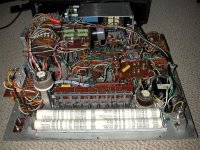
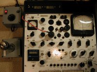
Pictures show addition of filamentary balance rheostat, disconnect for signal and additional 10V transformer to handle larger filamentary power triodes. A 211E Western Electric under test.
Using DC filtered bias (which is done on my Hickok 580A, and also on the RD/WE versions of the 539), will give inaccurate GM and plate current readings on Hickok's because the plate/screen supplies are unfiltered. I learned this with my 580A and can switch in/out the filtered bias. This is one reason why the roll charts are different between the 539B/C and the RD/WE versions, but using filtered bias you cannot compare results to actual plate curves. There are also issues with using DC for the filament if it is not center tapped to give +/-2.5V.
Pictures show addition of filamentary balance rheostat, disconnect for signal and additional 10V transformer to handle larger filamentary power triodes. A 211E Western Electric under test.
Attachments
Thanks for your advice & experience, mksj100 +++
I will experiment this tip, good idea - I thought about it, of course, but nulling a Gm WITHOUT signal reading as high as 4000-4500 was too much and suspect to me... But why not ? After all... The heater circuit of the Hickok 539 is probably very badly balanced, despite a well-balanced CT 100 ohms resistor (circa 0.1 ohms dip). I will see if I can null this parasitic Gm reading, then.
Suprisingly, my 539B seemed to be able to measure the Gm of the 300B, but the 539C still stayed completely off and delirious... This difference drove me to think that the 539C was suffering some kind of problem of phase addition or cancellation on one of its transformers : I will check it by comparison with my 539B with an oscilloscope, to be sure. In fact, I am not sure that my 539C hasn't been "serviced" or is still fully original.
I read your posts about your 580 in another forum, AFAIR, and yes, I tried that solution on my 539C in order to null the influence of AC heating on the direct heated-tubes : heater was DC filtered, biac was DC filtered, screen was DC filtered. No better... It was not a matter of inaccuracy : the readings were still completely off. But as you wrote it :
Heating in DC may not gave an improvement then, because the balance was probably not perfect due to the wiring, despite my use of a 75ohms/25W pot on the DC heating source...
I will dig further this problem of filament balance in the direction you point me.
Wait and see... & thanks again !
A+!
I ran into this issue in testing 211 and 845 tubes, as well as other filamentary tubes on my 539B. The solution is to zero out the filamentary noise with the signal off. This involves placing a switch to turn off the signal while the GM button is pressed and zeroing the meeting with a filament balance pot. I removed the stock centered tapped 100 ohm resistor and replaced it with a 100 ohm 25W pot.
I will experiment this tip, good idea - I thought about it, of course, but nulling a Gm WITHOUT signal reading as high as 4000-4500 was too much and suspect to me... But why not ? After all... The heater circuit of the Hickok 539 is probably very badly balanced, despite a well-balanced CT 100 ohms resistor (circa 0.1 ohms dip). I will see if I can null this parasitic Gm reading, then.
Suprisingly, my 539B seemed to be able to measure the Gm of the 300B, but the 539C still stayed completely off and delirious... This difference drove me to think that the 539C was suffering some kind of problem of phase addition or cancellation on one of its transformers : I will check it by comparison with my 539B with an oscilloscope, to be sure. In fact, I am not sure that my 539C hasn't been "serviced" or is still fully original.
Using DC filtered bias (which is done on my Hickok 580A, and also on the RD/WE versions of the 539), will give inaccurate GM and plate current readings on Hickok's because the plate/screen supplies are unfiltered.
I read your posts about your 580 in another forum, AFAIR, and yes, I tried that solution on my 539C in order to null the influence of AC heating on the direct heated-tubes : heater was DC filtered, biac was DC filtered, screen was DC filtered. No better... It was not a matter of inaccuracy : the readings were still completely off. But as you wrote it :
There are also issues with using DC for the filament if it is not center tapped to give +/-2.5V.
Heating in DC may not gave an improvement then, because the balance was probably not perfect due to the wiring, despite my use of a 75ohms/25W pot on the DC heating source...
I will dig further this problem of filament balance in the direction you point me.
Wait and see... & thanks again !
A+!
I have tested filamentary triodes that had GM readings in the 4000-5000 range and when I reversed the heater pin polarity and the GM meter went negative. Out of 50+ filamentary power tubes, the GM readings were all over the place unless you average the reading with the filament pins swapped or added a filament balance pot and 0 the meter with the signal off. That being said, you should not see these issues with balanced DC on the filament. I would expect the same "tube Imbalance" to be similar between your 539B and C. So it does sound like there is a problem in the 539C. I would first suspect an issue with your 5Y3 or the bridge balance. You should check the GM meter is at "0" with no grid signal.
You may have a balance/phase problem with your 5Y3 and/or 83 tube which can give erroneous readings. Before I went to solid state replacements for both tubes, I carefully matched the pulse peaks with an oscilloscope at magnification. Also the 6087 is a much better replacement in the Hickok tube testers over the standard 5Y3 because of the cathode sleeve. A word of note, is that with the 6087 or solid state 5Y3, that rectifier tubes should have the same readings for each plate. This is because there is no cathode asymmetry between the filament pins that is seen with the 5Y3 tube.
I long ago went to a moved to a solid state replacement for both the 83 tube and more recently the 5Y3 with excellent results in the Hickok 539B and 539C. Others that have used my recommended circuit for the 83 solid state replacement in other Hickok tube testers reported that they worked well and had the same GM reading before/after. Issues with phase balance and degradation over time are pretty much eliminated, although I do balance the diodes and zeners to make sure I have the same voltage drop in each leg.
The 5Y3 solid state worked fine in the Hickok 539B, but I would assume that in most other Hickok models that they need an additional heater load on the 5Y3 to give proper readings. A heat sinked 4 or 5 ohm 25W resistor across the filament pins should provide some additional loading. In some Hickok tube testers, I have swapped out the standard rheostat to a 350 or 400 ohm version to get more range, although I use a variac on all my tube testers. Because of the age of the transformers, there is less heat build up using a variac. It is important with any of theses changes/ SS replacements (especially the 5Y3) that you check all your voltages and verify they are correct (recalibrate).
Links to discussions on these solid state replacements.
Antique Radio Forums • View topic - Hickok 539B/C Solid State 5Y3 Rectifier Tube Replacement
Antique Radio Forums • View topic - Updated Hickok 539 Calibration document
I have a multitude of tube testers, but have switched to a uTracer curve tracer with an internal DC filament/Heater power supply. It is very accurate and much better at evaluating the performance characteristics of tubes at multiple operating points. The main limitation is a 300V 200ma max on the plate and 0 to -50V on the bias. It's results match my AVO's and bench setup to within a few percent, and it does this in a matter of seconds.
Attachments
Thanks mksj100 and neskor,
I am very busy these times so unfortunately I couldn't go further on my 539C problems, but evidently I read with great interest your tips... Thanks again !
I have a prototype of 83 SSS (Solid State Special) which incorporates 2 additional balance adjustments (plate balance / filament balance), simulates the heater consumption, and gives the required plate voltage. I will have to finalize it... But I never tested it while testing 300Bs, so I should, along with many other things that come to mind reading your advices.
Indeed : that's what I was thinking about too, but...
I agree. If direct heated tubes were not testable, they wouldn't be listed. But we find the 10, 45, 50, 300A, 300B on the 539B/539C roll charts or on supplementary Hickok factory data sheets. Moreover, my 752A and my 600 are able to test all of them with no issue.
I will retest everything, having your tips as an additional support and reminder, and try to find the issue these time.
I am quasi-persuaded that it is not cumulative errors, but really a local issue somewhere in the circuit. "Where ?" is the question...
I will be back there with further investigation elements ASAP.
A+!
I am very busy these times so unfortunately I couldn't go further on my 539C problems, but evidently I read with great interest your tips... Thanks again !
I have a prototype of 83 SSS (Solid State Special) which incorporates 2 additional balance adjustments (plate balance / filament balance), simulates the heater consumption, and gives the required plate voltage. I will have to finalize it... But I never tested it while testing 300Bs, so I should, along with many other things that come to mind reading your advices.
That being said, you should not see these issues with balanced DC on the filament. I would expect the same "tube Imbalance" to be similar between your 539B and C.
Indeed : that's what I was thinking about too, but...
So it does sound like there is a problem in the 539C.
I agree. If direct heated tubes were not testable, they wouldn't be listed. But we find the 10, 45, 50, 300A, 300B on the 539B/539C roll charts or on supplementary Hickok factory data sheets. Moreover, my 752A and my 600 are able to test all of them with no issue.
I will retest everything, having your tips as an additional support and reminder, and try to find the issue these time.
I am quasi-persuaded that it is not cumulative errors, but really a local issue somewhere in the circuit. "Where ?" is the question...
I will be back there with further investigation elements ASAP.
A+!
The ability to test the 300B tube seems to vary by model of tube tester, but many people recount not being able to test them on the Hickok 539B/C, and get better Gm readings (at least positive Gm readings) on other Hickok models. See this link: JACMUSIC.com • View topic - Hickok 539B and 539C oscillations . In order to test filamentary triode tubes you need to be able to balance out the filament noise, use a higher grid signal and/or use balanced DC on the filament, see Jac Music AN-08-Grid-Voltage-Measurement-Methods http://www.emissionlabs.com/Articles/APP-NOTES/AN-08-Grid-Voltage-Measurement-Methods-pdf
Hickok 539B/C factory supplementary data sheet for WE tubes, are:
filament = 5.0V
selectors = ER3200-0
bias = -14.0V
Gm range = D (6000 µMhos)
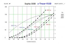
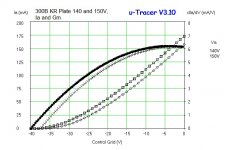
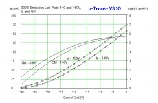
AVG MUT. COND. = 4000µMhos
Based on the plate curves done on a uTracer ( The uTracer, a miniature Tube Tester / Curve Tracer. ) performed at various voltages and grid bias settings (see attached information), it is very likely that the above 300B settings would exceed most 539B/C tube tester's plate capacities (some people claim they have tested to these levels). On the uTracer a Sophia 300B tubes tested at 150V on the plate and a grid bias of -14V gave a plate current ~84mA and a Gm of 5050, a KR 300B gave a plate current of 85-90 mA and a Gm of 6000, and an Emission Labs 300B XLS pushes 95-100 mA on the plate and Gm of 5300. So the Gm ratings are correct, but most likely this level of current is not feasible on this tester, certainly not mine based on degree of voltage sag (even with SS rectifiers). To compound the problem, when using an AC filament heater, without a filament balance pot, any readings would be worthless. The effect on the low grid signal on the 539B/C model at the 6000 µMhos is so substantial that often the Gm meter goes negative when testing. This becomes worse as the bias becomes less negative (so testing at -14V the Gm needle may swing negative, but positive at -20V), This can be adjusted to a reasonable degree with a filament balance pot (if added), but the Gm will still drift significantly do to filament noise dominating the grid signal. So even with a filament balance pot, as in my modified 539B and standard on the Hickok 580A it is possible to get reasonable Gm readings, but we are still talking maybe +/-20% of known values. That being said, the use of a bias of -14 at 150V on the plate will greatly overtax these testers and may result in damage. An interesting observation, is that the degree of error due to filamentary noise was less on the KR and Emission Labs 300B, most likely because of the filament configuration/structure .
Why do some Hickok's do better than others on testing the 300B, per one discussion, grid signal level. Older (and less expensive) Hickok's using higher grid signals, often 2.5V or even 5V do much better than those with lower signals that get lost in the filament noise. " The research I have done indicates that the higher grid signal you use, the better. For instance, the I177B testing a 2A3 with a 5-volt signal did a much better job than the Hickok 539C did using a .25-volt signal. As for a setting for the 300B (for the 539A) -- I checked and don't have it. Those tubes are so expensive that people gravitate towards the Triplett 3444 -- which is known to do a good job with the tube. If you need to work out a setting for the 539A, try to use a signal of at least 2.5-volts. If you try to use a .25 volt signal--your chance of an accurate reading would be poor." See this thread: Antique Radio Forums • View topic - Testing 300B tubes with Hickok 539A - settings??? .
There may be issues of oscillations being a problem for the poor Gm readings, but most of my Hickok's start to wheeze and turn over above 50 Ma. The 580a test data parameters are mostly designed to keep plate dissipations below 50Ma (even power tubes like the 6L6). The 539B/C and 580A come with ferrite beads, mine also have other mods to minimize oscillation, so doubtful in this case, and you get reliable Gm readings with a bias of -20. When testing the 300B at a bias voltage of -20 or -30, both the 539B and 580A give very acceptable results that are close to the uTracer curves at 140-150V (after adjusting for plate voltage sag on the 539B tester). In fact the Gm readings on the 580A using the standard filtered bias, are very close the uTracer values. Unfortunately the plate current doubles with default filtered bias vs. unfiltered (separate switch).
So what's so special about the Hickok RD-1575 / KS-15750 / WE electric versions of the 539; they use filtered DC on the bias just like the 580A, but there signal voltages are much higher. When the function switch is at (d) 6000 High, the signal is 5V, and even at (h) 6000 Low , the signal is 1V. They also use slightly higher (more negative) bias settings when testing the 300B. The 539B/C signal voltage is 0.5 at Gm 6000, the 580A is 0.278V. So we are talking 10-20 fold difference in signal voltages! Even with these setting, the Hickok RD-1575 / KS-15750 are pushing a lot more current through the plate transformer than the standard Hickok 539B/C because of the use of filtered bias with unfiltered plate. It is a bit of a complicated story as to why the plate current is (erroneously) so much higher, but it is best explained in this posted document "A tale of Two Tube Testers" A tale of two tube testers . I found this out the hard way with the Hickok 580A which gives correct Gm readings in its original factory form (once other problems are corrected) but gives exceedingly high plate current readings. With the 300B, the plate current readings read close to calibration with the unfiltered bias (an added modification), but with the standard filtered bias the current readings are almost double for the 300B. This is probably why the 539B/C have the option to measure the plate current, and where it was omitted from the Hickok RD-1575 / KS-15750. The readings would be gibberish.
Very few tube testers can test the 300B at realistic test parameters. It is possible to set-up a static test set-up with regulated power supplies, +/- DC filament supply that is center tapped to the cathode and derive Ia and Gm either by grid shift or injecting a measured signal and deriving the Gm. The latter method has been tested and matched (almost identical) the uTracer curves when using an external balanced DC supply for the heater/filament. Unfortunately the internal uTracer heater supply, does not work well with voltages less than 6V and can destroy the unit if hooked up incorrectly with filamentary heated tubes (i.e. don't use it). The internal heater supply also is not calibrated, so it tends to give more variable readings based on current and tube. Filamentary triodes when testing for Gm, for the most part require a balanced DC power supply to minimize noise and give correct plate curves relative to the bias voltage setting.
So what does this all mean. First off testing a 300B is a difficult challenge and in most cases will give erroneous readings. Probably the cheaper/older models do better because of significantly higher signal voltages. If you are going to insist on testing the 300B on these testers, consider using a bias voltage of -20V instead of -14V. If possible use a center tapped DC supply, otherwise consider adding a filament balance pot. The only other alternative is to test the tube in the standard ER32000 setting and then reversing the heater connections to BU32000 and than averaging the two Gm/plate current readings. I did this on about fifty 211 tubes tested in my 539B (using an added 10V filament transformer, the stock filament transformer on Hickok's is just too wimpy), worked on most of the tubes, but then there were those that had negative Gm readings. That is when I added the filament balance pot and grid signal disconnect to 0 the meter with the signal off. Do you give up anything at testing a 300B at a bias of -20V, probably not. I have several factory matched 300B tubes which I tested out to 200mA, readings at the -20V were just as closely matched as at higher voltages and different bias settings. So hopefully this helps others get a better handle on the issues of testing the 300B on the 539B/C.
Hickok 539B/C factory supplementary data sheet for WE tubes, are:
filament = 5.0V
selectors = ER3200-0
bias = -14.0V
Gm range = D (6000 µMhos)
AVG MUT. COND. = 4000µMhos
Based on the plate curves done on a uTracer ( The uTracer, a miniature Tube Tester / Curve Tracer. ) performed at various voltages and grid bias settings (see attached information), it is very likely that the above 300B settings would exceed most 539B/C tube tester's plate capacities (some people claim they have tested to these levels). On the uTracer a Sophia 300B tubes tested at 150V on the plate and a grid bias of -14V gave a plate current ~84mA and a Gm of 5050, a KR 300B gave a plate current of 85-90 mA and a Gm of 6000, and an Emission Labs 300B XLS pushes 95-100 mA on the plate and Gm of 5300. So the Gm ratings are correct, but most likely this level of current is not feasible on this tester, certainly not mine based on degree of voltage sag (even with SS rectifiers). To compound the problem, when using an AC filament heater, without a filament balance pot, any readings would be worthless. The effect on the low grid signal on the 539B/C model at the 6000 µMhos is so substantial that often the Gm meter goes negative when testing. This becomes worse as the bias becomes less negative (so testing at -14V the Gm needle may swing negative, but positive at -20V), This can be adjusted to a reasonable degree with a filament balance pot (if added), but the Gm will still drift significantly do to filament noise dominating the grid signal. So even with a filament balance pot, as in my modified 539B and standard on the Hickok 580A it is possible to get reasonable Gm readings, but we are still talking maybe +/-20% of known values. That being said, the use of a bias of -14 at 150V on the plate will greatly overtax these testers and may result in damage. An interesting observation, is that the degree of error due to filamentary noise was less on the KR and Emission Labs 300B, most likely because of the filament configuration/structure .
Why do some Hickok's do better than others on testing the 300B, per one discussion, grid signal level. Older (and less expensive) Hickok's using higher grid signals, often 2.5V or even 5V do much better than those with lower signals that get lost in the filament noise. " The research I have done indicates that the higher grid signal you use, the better. For instance, the I177B testing a 2A3 with a 5-volt signal did a much better job than the Hickok 539C did using a .25-volt signal. As for a setting for the 300B (for the 539A) -- I checked and don't have it. Those tubes are so expensive that people gravitate towards the Triplett 3444 -- which is known to do a good job with the tube. If you need to work out a setting for the 539A, try to use a signal of at least 2.5-volts. If you try to use a .25 volt signal--your chance of an accurate reading would be poor." See this thread: Antique Radio Forums • View topic - Testing 300B tubes with Hickok 539A - settings??? .
There may be issues of oscillations being a problem for the poor Gm readings, but most of my Hickok's start to wheeze and turn over above 50 Ma. The 580a test data parameters are mostly designed to keep plate dissipations below 50Ma (even power tubes like the 6L6). The 539B/C and 580A come with ferrite beads, mine also have other mods to minimize oscillation, so doubtful in this case, and you get reliable Gm readings with a bias of -20. When testing the 300B at a bias voltage of -20 or -30, both the 539B and 580A give very acceptable results that are close to the uTracer curves at 140-150V (after adjusting for plate voltage sag on the 539B tester). In fact the Gm readings on the 580A using the standard filtered bias, are very close the uTracer values. Unfortunately the plate current doubles with default filtered bias vs. unfiltered (separate switch).
So what's so special about the Hickok RD-1575 / KS-15750 / WE electric versions of the 539; they use filtered DC on the bias just like the 580A, but there signal voltages are much higher. When the function switch is at (d) 6000 High, the signal is 5V, and even at (h) 6000 Low , the signal is 1V. They also use slightly higher (more negative) bias settings when testing the 300B. The 539B/C signal voltage is 0.5 at Gm 6000, the 580A is 0.278V. So we are talking 10-20 fold difference in signal voltages! Even with these setting, the Hickok RD-1575 / KS-15750 are pushing a lot more current through the plate transformer than the standard Hickok 539B/C because of the use of filtered bias with unfiltered plate. It is a bit of a complicated story as to why the plate current is (erroneously) so much higher, but it is best explained in this posted document "A tale of Two Tube Testers" A tale of two tube testers . I found this out the hard way with the Hickok 580A which gives correct Gm readings in its original factory form (once other problems are corrected) but gives exceedingly high plate current readings. With the 300B, the plate current readings read close to calibration with the unfiltered bias (an added modification), but with the standard filtered bias the current readings are almost double for the 300B. This is probably why the 539B/C have the option to measure the plate current, and where it was omitted from the Hickok RD-1575 / KS-15750. The readings would be gibberish.
Very few tube testers can test the 300B at realistic test parameters. It is possible to set-up a static test set-up with regulated power supplies, +/- DC filament supply that is center tapped to the cathode and derive Ia and Gm either by grid shift or injecting a measured signal and deriving the Gm. The latter method has been tested and matched (almost identical) the uTracer curves when using an external balanced DC supply for the heater/filament. Unfortunately the internal uTracer heater supply, does not work well with voltages less than 6V and can destroy the unit if hooked up incorrectly with filamentary heated tubes (i.e. don't use it). The internal heater supply also is not calibrated, so it tends to give more variable readings based on current and tube. Filamentary triodes when testing for Gm, for the most part require a balanced DC power supply to minimize noise and give correct plate curves relative to the bias voltage setting.
So what does this all mean. First off testing a 300B is a difficult challenge and in most cases will give erroneous readings. Probably the cheaper/older models do better because of significantly higher signal voltages. If you are going to insist on testing the 300B on these testers, consider using a bias voltage of -20V instead of -14V. If possible use a center tapped DC supply, otherwise consider adding a filament balance pot. The only other alternative is to test the tube in the standard ER32000 setting and then reversing the heater connections to BU32000 and than averaging the two Gm/plate current readings. I did this on about fifty 211 tubes tested in my 539B (using an added 10V filament transformer, the stock filament transformer on Hickok's is just too wimpy), worked on most of the tubes, but then there were those that had negative Gm readings. That is when I added the filament balance pot and grid signal disconnect to 0 the meter with the signal off. Do you give up anything at testing a 300B at a bias of -20V, probably not. I have several factory matched 300B tubes which I tested out to 200mA, readings at the -20V were just as closely matched as at higher voltages and different bias settings. So hopefully this helps others get a better handle on the issues of testing the 300B on the 539B/C.
Attachments
Prior post on discussion by ChuckD on filtered vs. unfiltered Bias DC interaction with "unfiltered DC plate voltage" and effects on plate current and Gm in Hickok tube testers. Antique Radio Forums • View topic - Hickok Gm measurements . The Western Electric 539 tube tester models had filtered DC bias and screen voltage, probably due to many frame-grid tubes need to be tested using cathode bias which requires a cathode resistor/bypass capacitor. The filtered DC bias can give erroneous current readings (and possibly Gm) on the Hickok 580/A, TV-2, and the WE15750 models, but the Gm is close. The error in plate current was more significant with the 300B, than other indirectly heated tubes like the 6SN7. Evidently this is why the data sets are not interchangeable for say the 539B/C and the RD1575/WE15750, and another reason why values of a tube's performance can vary significantly between different tube testers.
Thanks a lot mksj100 and kevinkr for taking the time to post your advices and tips about my 539B/C-300B measurements mysteries...
I see that you preceeded me more or less on that peculiar measurement issue and draw before me many conclusions that I come too, experimenting by myself. So I agree with all your statements and inputs, and I record them carefully.
The only supplementary thing that I (can I say we ?) do not undestand on my 539C is that when DC filtered 5.0 Volts (40000µF + choke) is applied to the 300B heater, the issues are not eliminated nor reduced (negative pointer deviations, off Gm values, etc...).
For information, I checked that my 539B and C were able to test 6550 and KT88 at a plate current of circa 90-100mA (with Gm values at circa 11000) and the 300B tests at 60-70mA (no matter the nonsense deviation of the pointer with the 300B). These plate current values are very close between the 539B and C for a same tube sample (say +/- 3mA difference at least) . I find circa the same values on my 752A. So testing with a plate current over 50mA is doable - I remember that the plate voltage dropped to 130-140V under these conditions, with a 5Y3 and a 83. Sorry, I do not have my notes on hand...
Awfully, these times I do not have the time to make tests according to all of those interesting tips from you on my 539B and C because of professional matters, but indeed I will, as soon as I will be able to do anything else than solely posting...
kevinkr : if you have the possibility to cross-check with you 539B a bunch of "known good" 300B from you U Tracer, and let me know if you have issues like on my 539C or not, I would be very interested to know the results, you guess it...
Thanks again & A+!
- Status
- This old topic is closed. If you want to reopen this topic, contact a moderator using the "Report Post" button.
- Home
- Design & Build
- Equipment & Tools
- testing 300B on Hickok 539B/C