Yeah, I remember seeing the picture of the mods and the explanation, however I cannot do much with "back to back depletion mode FET's", because that's way beyond my abilities.
I was hoping for a more specific description with schematic so mere mortals, me included, can learn from it and try to duplicate it.
I was hoping for a more specific description with schematic so mere mortals, me included, can learn from it and try to duplicate it.
Found it, it was not easy to find (for me?):
http://www.diyaudio.com/forums/tube...sound-card-interface-ideas-suggestions-8.html
I didn't have the impression that this was a finished discussion/design.
In any case, it looks like the bulbs are a better solution, but I agree with Pete, they need to be 120V to have enough resistance, right? I think that halogen lamps are probably best because they have leads.
I found a possible at Amazon.com. Search for 5XG8-120V-20W
They are reasonably priced too.
At 120V 20W the resistance is probably high enough. I don't think 100W is usable for this purpose?
20W is too big - it will have very low resistance.
Most tiny xmas lights are intended for series string operation so they're pretty low resistance too. If you can find one that works in a parallel string, it should be good.
The only bulb I could find that meets the requirements and is readily available is the type 120MB:
120MB Chicago Miniature | Mouser
No wires, though. Easy enough to solder some on.
Wire versions do exist, but they're hard to find. Look for something like a 120V 25mA rating.
Pete
Hello, I've found an A4 sheet of Ultraperm 80 I had bought 2 years ago to screen my ATEST enclosure but superbly miss-laid it in between.
2 questions.
1) Screen top, bottom AND front/rear panels of the casework?
2) Is there a recommended ground point to take the screens back to on the PCB?
Newbie-ish questions I know but I am!")
Cheers,
DTB.
2 questions.
1) Screen top, bottom AND front/rear panels of the casework?
2) Is there a recommended ground point to take the screens back to on the PCB?
Newbie-ish questions I know but I am!
Cheers,
DTB.
Are the screens/shields carrying any signal?
If so then they MUST remain in the signal circuit loop.
That loop consisting of Signal Flow and Signal Return must be a pair of close coupled wires and MUST be continuous without a break.
If the screen/shield does not carry any signal, then there MUST be two wires inside the screen to carry the Flow and Return signals. This screen/shield must be connected to the chassis at the entry and expose the minimum of signal wire as they too enter the chassis.
At the PCB the two signal wires, i.e. two for each channel, must both be connected to maintain that close coupled pair. Again the screen should leave the minimum of exposed signal pair.
I still use mine occasionally. It is a very useful interface. Currently, I don't think there is anything better than Pete's interface.
Most of the time I get what I need from my HP339a Analyzer. Mainly because I am very comfortable with it. I also have a lot of confidence in my results. Connect a few cables, turn a few knobs, read the meter, record the results.
Pete's interface is a fun build. I don't think you made a mistake.
Most of the time I get what I need from my HP339a Analyzer. Mainly because I am very comfortable with it. I also have a lot of confidence in my results. Connect a few cables, turn a few knobs, read the meter, record the results.
Pete's interface is a fun build. I don't think you made a mistake.
Just picked up a board as well. Have ordered parts. Always dreamed of having decent measuring set-up, I think this is the ticket. Better specs and less expensive than most legacy dedicated analysers. Acquired the HP 8903B by some miracle, and built up a xeon-based workstation that may soon have a PCIe sound card How is the Juli@ ?
Found the Red Lion meter on EPay for much less than the almost 90 bucks Canadian from Mouser / Digi-key. I think there are better DC/DC converters on the market now, the XP Model JCA0305D03 from Digi-key has decent specs. I expect there will some tweaking required to minimize power rail noise.
Anyways if there are still some builders out there, I'm about to break out the soldering iron this weekend. I will be happy to share the build experience, or if others have any new tips???
How is the Juli@ ?Found the Red Lion meter on EPay for much less than the almost 90 bucks Canadian from Mouser / Digi-key. I think there are better DC/DC converters on the market now, the XP Model JCA0305D03 from Digi-key has decent specs. I expect there will some tweaking required to minimize power rail noise.
Anyways if there are still some builders out there, I'm about to break out the soldering iron this weekend. I will be happy to share the build experience, or if others have any new tips???
Just picked up a board as well. <snip>?
Please share your tips. I just ordered Pete's board and a Red Lion display on eBay. Placing an order for the BOM from Mouser soon.
The only bulb I could find that meets the requirements and is readily available is the type 120MB:
120MB Chicago Miniature | Mouser
No wires, though. Easy enough to solder some on.
Wire versions do exist, but they're hard to find. Look for something like a 120V 25mA rating.
Pete
I'm guessing that if I drilled a hole in my enclosure and used a lamp holder for the T-2 bulb, that would act like an antenna for 50hz noise.
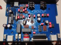
Hi Tazz your results are fantastic, can you please elaborate on the mods you've made and the pictures that you've posted; like what have you soldered onto the underside of the 6mm sockets etc. I've recently finished one of these interfaces and I'd like to get it performing as well as yours.
I think what's soldered on the back of the pcb, under the 6mm sockets, is shielding. But I'm not sure where the RFI filter capacitors he mentions are located. I'm trying to get a handle on everyone's enhancements for Pete's SCI before I start mine.
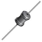
Can you cut the trace between F1 and D9 and solder a small 12uH choke on the bottom side of the board to replace the cut trace?There's some RF energy eminating from the INPUT of the DC-DC converter -- I posted on this 2 years ago -- you can eliminate it by using a small value choke on the input lead -- if you're using Pete's board you could replace the fuse with a choke.
I ordered this inductor from Mouser.
Attachments
Last edited:
Got my interface finished but it needs a few tweaks. I need to add shielding to take care of 60hz noise. I could also use some help understanding the inputs and outputs for the interface. I understand the input and sound card in but what about GEN OUT and SC out? How do you set up the switch stops?
Last edited:
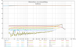
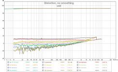
Audio passed through light bulbs
I read the posts stating that the noise floor can be reduced by substituting light bulbs for the R2 and R16 resistors which are in series with the audio before the first active stage. Has anyone evaluated the light bulb concept for distortion performance? I expect that a resistor is going to be more linear than a light bulb at audio frequencies. What are the facts found about this?
I read the posts stating that the noise floor can be reduced by substituting light bulbs for the R2 and R16 resistors which are in series with the audio before the first active stage. Has anyone evaluated the light bulb concept for distortion performance? I expect that a resistor is going to be more linear than a light bulb at audio frequencies. What are the facts found about this?
The 49k9 and the diodes are there to protect your opamps from overload of the inputs.
If you know that you will never overload the inputs, then you can reduce the resistor values significantly.
The advantage to using a tungsten filament light bulb is that it increases it's resistance massively as current is increased. That allows one to start with a lower resistance and during the overload incident, the bulbs increase resistance to reduce the heating within the diodes so that they don't fail. But that is after the event.
A 25W 240Vac bulb has a cold resistance of ~190ohms. That is very little protection until the filament heats up. The fully hot filament is ~2300ohms. That too is very little protection.
Maybe worth looking at using TVS or something similar across the inputs. It would also be worth looking at a switch of the push and hold type to select the lower sensitivities. Hands off always defaults to the 200V scaling.
Last edited:
Hey.
I've been reading through this thread, and I'm very interested in this interface.
But I'm quite a bit of a noob on the while THD measuring.
I've been messing around a bit with Visual Analyzer, and also Arta.
However, I'm not entirely sure how to measure THD - in my case on my soundcard (Motu ultralite avb).
Would someone be willing to write a short howto?
- Home
- Design & Build
- Equipment & Tools
- Test & Measurement interface for Soundcard