Thomas: How do you split stylus azimuth and generator azimuth in your setup?
I don't. I set for generator azimuth. If stylus is off, I discard that stylus and buy an new.
Not sure what you are referring to here. Do you mean the azimuth/crosstalk of the cutting lathe, I agree this has to be perfect? Phase lock to the 1kHz signal is easy so noise, etc. can be ignored. The current SOTA allows even the most basic PC to do some very sophisticated signal analysis on the test tracks with free software.
Yes, and test record vary using the same azimuth setting. Some test records do not get lower than -30 dB no matter how you set azimuth, other like the Ortofon goes lower. So I tend to trust the test record where I can get the lowest readings both channels.
ok in that case why not a null test wtih a mono tone for generator azimuth? look at L-R, either electrically or reverse strapping the cartridge.
You can do that too, but you need to have equal channel balance I think? For left-right signals you can look at the phase of the crosstalk signal also. I do not remember so much when I did this quite some time ago now, I just check with a left-right signal today.
I think everything is fighting everything else, but having channel balance as close as possible seems to be a very good starting point. But I think there is some tail chasing as everything inter-relates. Which makes it valid to discuss as a workflow for the coding phase.
This is a subject that I think folks tend to over and under think at the same time. The standard test is at 1kHz but crosstalk degrades a lot at higher frequencies, the net audibility of one alignment over another at the finest scale remains an open question.
BTW there is no way to determine the crosstalk limit of a given test LP without a perfect reference cartridge (or maybe an optical scan). Dr. Feickert found one cartridge that was >-40db but most cartridges bottomed out at closer to -30db on the same LP. This is a case where fortuitous cancellations can fool you.
BTW there is no way to determine the crosstalk limit of a given test LP without a perfect reference cartridge (or maybe an optical scan). Dr. Feickert found one cartridge that was >-40db but most cartridges bottomed out at closer to -30db on the same LP. This is a case where fortuitous cancellations can fool you.
I think everything is fighting everything else, but having channel balance as close as possible seems to be a very good starting point. But I think there is some tail chasing as everything inter-relates. Which makes it valid to discuss as a workflow for the coding phase.
channeö balance yes, but this is something you cannot set other than by buy a bunch of cartridges and then select the one with best balance. You can also adjust if you have a balance control on your RIAA.
Here are the results from three records in dB (difference in brackets), 1 kHz signal
Tacet
R->L: -5.5/-30.4 (-24,9, out of phase)
L->R: -4.1/-32.8 (-28.7, out of phase)
Ortofon
R->L: -6.3/-38.8 (-32.5, close to in phase)
L->R: -5.3/-46.8 (-41.5, close to out of phase)
UATLP
R->L: -5.5/45.7 (-40.2, in between)
L->R: -5.2/-36.1 (-30.9, out of phase, not pure sine)
So which one should I trust the most?
Last edited:
Well at least one of mine had 0.5dB channel balance out the factory, stylii that failed that were sold as the lower spec model with 0.75dB balance. Only difference is the stylus, same internals for both.
That is probably so and something I found also with different stylii but same body.
Here are the results from three records in dB (difference in brackets), 1 kHz signal
Tacet
R->L: -5.5/-30.4 (-24,9, out of phase)
L->R: -4.1/-32.8 (-28.7, out of phase)
Ortofon
R->L: -6.3/-38.8 (-32.5, close to in phase)
L->R: -5.3/-46.8 (-41.5, close to out of phase)
UATLP
R->L: -5.5/45.7 (-40.2, in between)
L->R: -5.2/-36.1 (-30.9, out of phase, not pure sine)
So which one should I trust the most?
Your guess is as good as mine. Have you tried the exercise of tuning the azimuth assuming each is perfect and listening to each result. Tedious I know, but that's the fun of vinyl. One thing I didn't think of, a tool that was able to identify an actual manufacturing defect (and gave a valid reason for a refund) would be of use to every serious user.
Last edited:
So that does suggest stylus azimuth matters more than generator?
Ref the test records, it's late and I'm tired after a long week, but something concerns me about the Ortofon test record results as one set of measurements is out of phase and the other in phase. I might be missing something but I can't see anything causing that other than a cutting error. In this test one wall is modulated and the other smooth, so the 'undriven' channel just has the stylus sliding up and down the smooth side. If the generator and stylus azimuth are perfect you will get lowest level.
Now if the generator is twisted what will the phases be. Sitting here thinking about it without the benefit of a piece of paper I might believe that the phase flip will occur, because the twist will put one channel above the 45 degree dead line and the other below. But the coils are wired antiphase inside the cartridge.
I need to draw this....
So that does suggest stylus azimuth matters more than generator?
Ref the test records, it's late and I'm tired after a long week, but something concerns me about the Ortofon test record results as one set of measurements is out of phase and the other in phase. I might be missing something but I can't see anything causing that other than a cutting error. In this test one wall is modulated and the other smooth, so the 'undriven' channel just has the stylus sliding up and down the smooth side. If the generator and stylus azimuth are perfect you will get lowest level.
Now if the generator is twisted what will the phases be. Sitting here thinking about it without the benefit of a piece of paper I might believe that the phase flip will occur, because the twist will put one channel above the 45 degree dead line and the other below. But the coils are wired antiphase inside the cartridge.
I need to draw this....
Well as I understand this, given that the silent channel does not have any signal recorded, you will get a vector either vertical or lateral if it is not perfectly aligned with the groove. I recall I can get either in or out of phase if I twist the azimuth also with other test LPs.
I don't know what the effects are regarding stylus azimuth but I guess noise is one.
Your guess is as good as mine. Have you tried the exercise of tuning the azimuth assuming each is perfect and listening to each result. Tedious I know, but that's the fun of vinyl. One thing I didn't think of, a tool that was able to identify an actual manufacturing defect (and gave a valid reason for a refund) would be of use to every serious user.
I have in the past, but it is a real tedious work since I have the Moerch UP-4 unipivot and there are very tiny changes that are needed for improving a few more dB. Listening is the most tedious work, so I prefer to measure it and leave it when good enough.
I looked at the track list and made a revised version here:
Tracklist -V4.ods - Google Sheets
This is version 4. Please have a look.
A few levels were adjusted, I added some Farina chirps that are used by modern software for FR, distortion and impulse measurements. Basically a fast log sweep lasting 300 ms. Also added a lathe speed test, which is 5680 cycles of a 3150 Hz sine. If the lathe speed is a perfect 33 1/3 RPM then this tone should go around the disk once and overlap by exactly 10 cycles. We can check the overlap with a microscope and know the lathe speed to about 0.01%
What I don't see is a drag test. Any ideas of what it should be?
A note on levels: I don't know how hot some of the tracks can be cut, that's something I was hoping to talk to a mastering/cutting engineer about.
What I don't see is a drag test. Any ideas of what it should be?
A note on levels: I don't know how hot some of the tracks can be cut, that's something I was hoping to talk to a mastering/cutting engineer about.
Not sure on the drag test. I think I just came up with an easy cheap LP centering technique that anyone can do, I'm going to try it tonight (with pictures).
For drag I had assumed a locked groove with a suitable modulation on that is an even number per revolution. You record in the groove during a section of coastdown.
If you are using a stopwatch then a silent groove will do. Modulated is for when you want the PC to do the legwork. The problem with that approach is the initial calibration with arm up to get a measure of bearing friction. For DD you can pick off the FD servo signal with some jiggery.
No free lunch as ever.
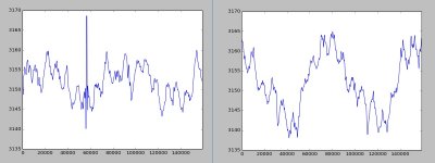
OK here it is. I placed a cheap USB microscope over my cartridge as it was playing and watching on the screen I thought of retrograde planetary motion.
So here is my idea.
1) Ream out the hole on the LP just enough to find the true center
2) Get some 1" or so thin SS washers and ream their center holes to be a tight fit to your spindle
3) Put a tiny dot on the top of your cartridge, it does not matter how well centered it is. You could image any small feature on the cart if you want and in fact no alignment here is critical
4) Imaging the dot with a USB microscope rotate the platter by hand to find the min and max point of the wobble (the groove pitch is a small error to be aware of)
5)Mark with a piece of tape on your screen the min and max point of one revolution
6) Park the LP at one or the other and taking care to move the LP along the stylus/spindle radial axis split the difference. Two iterations should be more than enough.
7) Glue the washer in place to save the alignment
Picture is one iteration simply using the play in the Dr. Feickert LP (there was not enough play to fully fix it).
Attachments
- Home
- Source & Line
- Analogue Source
- Test LP group buy