So I would personally trust them with money/information/getting things done as they have proven it again and again.
Very sad...
Agreed.
")
I have no capacity to add anything of significance - so I've just been reading this thread.
I just look forward to being able to buy the end result in due course.
Andy
Yeah.
Back on centering and serious apologies if I missed something. GZ spec 0.2mm so pending them answering the question on if they can do any better we need to consider 2 things
1. How do we measure how far out it is?
2. How we adjust.?
First point is slightly easier to consider so lets look at that first as I am still working out how to nudge a record 0.05mm if precision filing of the hole is not an option.
There are at least 3 ways to do this
-mechanically as per the Nakamichi TX-1000 (too complex)
-optically with a frikken laser beam (or led pointer)
-sonically by looking at the output on a polar plot
Optical seems to have a lot going for it. Stick a laser on the bearing yoke and play record. If your TT is in the right place you will have a beam moving on the far wall giving you amplification of the error. Bit of trig and you can work out your adjustment vector, hopefully without blinding yourself/wife/cat etc. I'm going to order a pointer and see if it's actually usable for this.
Sonic solutions would rely on the fact that we can overlay rotations on top of each other. We would just need a TDC measurement to calculate the angle for the correction vector. But I don't think we concluded if we could include a click for this or use an external once per revolution input?
Back to mulling point 2...
Am I missing something or would an outer edgeish lock groove with say a 7500 hertz tone not just show centering but also wear? A click at the start/end would also be useful.
I wouldn't go much higher in frequency in case old geezers want to use it.
We could also discuss cabin fever, but spring is coming.
I wouldn't go much higher in frequency in case old geezers want to use it.
We could also discuss cabin fever, but spring is coming.
Forgive me if this seems a stupid question but it has returned to me so many times I have to ask. When records are pressed and taken off the press, is the groove body always concentric with respect to the outside circumference of the disc?
If so, couldn't we simply order the records un-punched and do that job separately?
If so, couldn't we simply order the records un-punched and do that job separately?
In your dreams
Give me a break the posts are there as record, you're the dreaming one. We cooperated or so I thought so we did not need your code and the plots lined up and anyone can go back and find the posts in the thread, what has turned you so nasty continues to baffle me.
Last edited:
Well, at this point we should get back to the record.
It seems that having the hole punched at the exact center is an issue that we can't answer. The information must come from those who manufacture LPs. May as well drop that for now and come back to it when we get information.
It seems to me that we have no choice but to accept the best tolerance attainable from the supplier. Again, it is something we can't change, so it isn't worth getting all worked up about it. At the end of the day, we will have a test LP better than most but with useful signals on it. That is good enough for me. Same as my test equipment which is on average 20 years old. Not much I can do about that either, so I can't worry about it.
Why not list the issues we need to deal with and attack them one by one? By the time we sort that list out, we can press some test albums.
-Chris
6.3kHz might be better. Question, how would it show wear? The problem with wear is that it would seem that the stylus hits the groove wall before the HF rolls off that much. Unless I missed something.
Record wear would have level drop and distortion rise.
Sadly not as the outside circumference is cut by the machine after pressing. We could punch our own if we had a locked groove, a suitable microscope and a cutting setup that was accurate to IIRO 0.05mm. (which we don't have).
Ah, I see. I made a punching die in Front Panel Design in about 5 minutes. Their accuracy isn't high enough but laser cutting can be tight to something like 30 microns. I got all excited but now see that ain't the way. Thanks
. . . .Why not list the issues we need to deal with and attack them one by one? . . . .-Chris
+1
It seems that having the hole punched at the exact center is an issue that we can't answer. The information must come from those who manufacture LPs. May as well drop that for now and come back to it when we get information.
I think this may be somewhat of a dry hole. In my experience, centering the hole to minimize eccentricity on one side of the LP does not necessarily guarantee the obverse side will also be concentric. If this is something you are trying to optimize, then perhaps it would be best to place any tracks affected by it on one side with instructions to minimize the error with respect to the side of the LP that is most sensitive, i.e. frequency stability and similar tests?
BTW, count me in for at least one of the test disks, if/when they become available.
FWIW, I think Scott's software not only does a better job of resolving instantaneous frequency, it does a much better job of the presentation of results. Not to mention, he was kind enough to make it open source, which can only lead to a better implementation; he should be commended for his unselfish efforts.
If cover art is still a going concern, I've attempted to contact the site I previously posted, via phone (negative contact, not even voice mail), and e-mail (no response as of yet). I claim no copyright or IP protection for the photo I uploaded of my cartridge.
Last edited:
FWIW, I think Scott's software not only does a better job of resolving instantaneous frequency, it does a much better job of the presentation of results. Not to mention, he was kind enough to make it open source, which can only lead to a better implementation; he should be commended for his unselfish efforts.
I appreciate your comments, but I think we should move away from the current conflicts and get some tangible results. It was never a contest for me but a nice brain exercise plain and simple.
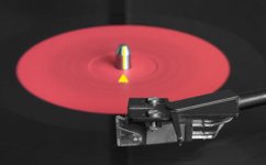
For Record eccentricity test there would be too many variables right ? Like not each and every turntable record spindle would be precise. Not All record hole would be precise, after all it is plastic. So would following method work ? see pic attached.Back on centering and serious apologies if I missed something. GZ spec 0.2mm so pending them answering the question on if they can do any better we need to consider 2 things
1. How do we measure how far out it is?
2. How we adjust.?
1) We put marking on record label as near to the spindle as possible. Shown in yellow.
2) Mark the spindle with fine marker pen. Place test record so that label mark and spindle marks align.
3) Measure locked in groove tone.
4) Rotate the record 180 degrees so that the label mark is exactly opposite.
5) measure locked in groove again.
6) whatever modulation eccentricity on the record will be 180 degrees different and can be detected in polar plots. the 'Rest' of the eccentricity will be that of turntable spindle or Bearing or motor etc. All we have to do is differentiate the two exact eccentricity 180 degrees apart 'against' another eccentricity.
Simple and workable ?
Attachments
A sleeve of thinish walled tubing 1/4" ID that slips over standard center post, and slightly oversized record hole (to match Tubing OD).
Use the sleeve to get standard centering, remove the sleeve for manual/precise groove centering.
The record could be supplied with standard center hole version, and a quick drilling process and sleeve supplied as an optional version.
Is there a standard hardware shop item that has suitable dimensions ?....then all that is required is spec of of suitable drill size for diy mod.
I'm late to the party, I have taken a look back a few pages and I am seeing a camel being designed by a committee.
I sure would like a useful test record at economical price so I'm in depending on what the result is.
What are the requirements for a modern test record, and where on the record are they best placed ?.
Dan.
Last edited:
That's not reasonable, spaceistheplace. IIRC, you haven't actually contributed content to the test record? Then in my reckoning, your interest can only be as a buyer?
LD
If you think the liquid is all that’s sold with a drink, you haven’t been following Coca Cola for the past hundred years.
Although if you feel it’s not a “valid contribution”, I can accept that.
The dither is sort of built in with vinyl, isn't it?
I would think so.
OK.Please give us a list of what you claim is uniquely yours, and it will not be included. Easy enough.
Uniquely :
1. Level versus f sweep tests
2. Fixed amplitude compliance tests
3. Lock groove wear tracks
4. Constant velocity/groove angle cartridge linearity/trackability/compliance tests
5. Triangle apex curvature traceabilty/wear accelerations tests
6. 10kHz tone burst trackability tests
7. Click impulse stimulus test cart/arm resonant damping tests
8. Stylus drag/groove friction tests
I've taken these down (again) from the tracklist and removed the placemarkers.
And, I helped develop or commented on many of the remaining test tracks, some of which won't work as they are defined BTW. What remains of the tracklist is disappointing, IMO.
My concern was to restrict the initial run to members only and 250 units, and I still can't see a good reason not to do that. It's what you'll do anyway. My motivation remains to avoid exploitation of philanthropy, not to stifle it.
Neither the concept of the polar plot, nor its copyright, is mine. AFAIK it belongs to Paul R on pink fish media, in case you guys wish to develop it into something. I hope so. The reason I didn't open source my FM detector code is because in coding it for myself a few years back, I accidentally stumbled on a method which performs remarkably accurately remarkably quickly. Since that's original I would like to explore whether it's unique and potentially worthy of proper disclosure. It potentially still has professional kudos, if not fiscal, value.
The test tracks, on the other hand, are only interesting to people looking to tune the fine points of vinyl playback, and have no fiscal value. Nevertheless, sales of the test record, in combination with polar plot SW, could be big, IMO. I can only guess this is the elephant in the room, that might help make sense of an otherwise silly course of events.
Lastly, I hold immense respect for the technical capability and knowledge and general contribution of everyone on this forum, especially long standing 'senior' members. Thank you.
LD
LD
- Home
- Source & Line
- Analogue Source
- Test LP group buy