Although a resonantor might not sit well on first mention, and I can easily imagine using one poorly sounding horrible, but to use it to tune carefully , well, it is better to find out then to imagine.
A ported box is a resonator, no? So we use that approach a lot already. Sometimes they sound great sometimes not. That says to me that proper implimentation is important. That's a good thing- means that we can tweak until we get it right! Or it turns out to have problems.
As always the only way to tell is to try it.
Variac said:A ported box is a resonator, no?
Indeed. I do tend to avoid any ported box that is not somehow removed away from being a bass reflex.
dave
Dave, are you sure what you are talking about? Forgive me if I'm wrong but this link below is is so pedagogic that even I understand.
The Helmholtz described by this thread below, works like a passive "mechanical" filter in order to take away peaks from the pipe. Pity it's not written in English.
Lots of measuring and pictures though!
http://www.hififorum.nu/forum/topic.asp?TOPIC_ID=45145&whichpage=1
Cheers
Peter
The Helmholtz described by this thread below, works like a passive "mechanical" filter in order to take away peaks from the pipe. Pity it's not written in English.
Lots of measuring and pictures though!
http://www.hififorum.nu/forum/topic.asp?TOPIC_ID=45145&whichpage=1
Cheers
Peter
peterbrorsson said:Dave, are you sure what you are talking about? Forgive me if I'm wrong but this link below is is so pedagogic that even I understand.
I think so... in the thread you linked he says (i think) that he is building a design out of one of those German hobby magazines i mentioned (Hobby HiFi, nr 6 2004)
It is not a mechanical filter, it is an acoustic one. On the face of it, it makes total sense. Remove energy from the back of the cone at one of those undesirable harmonic frequencies of the fundemental 1/4 wave. I just wonder what affect that removal has on the driver loading -- and the tuning of these is quite tricky.
I would use other tricks 1st -- for instance an appropriate offset kills the 1st undersirable harmonic (or more accurately reduces how much it is excited), and a line taper or mass-loading improve the low-pass function of the line. In a BIB only the 1st is really applicable.
dave
It is not a mechanical filter, it is an acoustic one. On the face of it, it makes total sense. Remove energy from the back of the cone at one of those undesirable harmonic frequencies of the fundemental 1/4 wave. I just wonder what affect that removal has on the driver loading -- and the tuning of these is quite tricky.
Yes, I can see the term acoustic filter makes sense, I'm not so experienced in this (understatement
") )
)Regarding the driver loading, there are graph's of impulse and impedance in the pipe further in the thread. It's also written that he has made much more measuring than posted in the thread. Yes, must be tricky to tune it for sure!
But I'm not able to keep up this discussion as I've not enough knowledge!
I only know that the thread starter, Lennart, put tremendous time and efforts in his projects. He's more known for his tube amplifiers.
Cheers
Peter
Yes looks a whole lot of info in there. My not being able to read anything but English severely limits my understanding of the context of the measures.
As well, he is only showing the gross FR. There are lots of subtleties that these kind of measures are unable to show.
dave
As well, he is only showing the gross FR. There are lots of subtleties that these kind of measures are unable to show.
dave
Well, here's some pornographic pictures to the machine fetischists or however it spells
http://www.hififorum.nu/forum/topic.asp?TOPIC_ID=56262
http://www.hififorum.nu/forum/topic.asp?TOPIC_ID=56262
peterbrorsson said:Well, here's some pornographic pictures to the machine fetischists or however it spells
http://www.hififorum.nu/forum/topic.asp?TOPIC_ID=56262
He's obviously worked up quite an appetite, look at the size of that pizza.

Jeff
I think that a resonant chamber, if designed correctly , isn't going to change the character much, After all it is still basically the same BIB.
It might also be better to try and repair the dip to a point, but not have it pushed all the way up to flat response. That way the effects of the dip are lessoned, without being as noticable.
Can these resonators be designed with box design software somehow by only entering certain parameters or something?
Or:
How does one calc a Hemholtz?
Also:
So there is the Resonator, which augments the sound at certain frequencies which is a hollow cavity?
and an Acoustic Filter which is the same cavity stuffed? which reduces the sound at certain frequencies,
Somehow the Filter seems like it would be more benign, but the resonator would seem to be more needed with the BIB.
How do you adjust the width of the filter? tuning the port?
Greets!
A Helmholtz resonator is a band stop (notch) filter, so how can it fill in a cancellation dip? http://www.kettering.edu/~drussell/GMI-Acoustics/Filters-Frame.html
GM
A Helmholtz resonator is a band stop (notch) filter, so how can it fill in a cancellation dip? http://www.kettering.edu/~drussell/GMI-Acoustics/Filters-Frame.html
GM
I'm with GM on this... my understanding of these was that they are used to attenuate certain frequencies.
The idea is to attenuate those frequencies inside the box that would otherwise cause constructive (peaks) or destructive (dips) in the frequency response due to the change in phase wrt the front radiation. In practise they are used to attenuate the 1st and/or 2nd non-desirable harmonics of the primary 1/4 wave resonance so that ripple is reduced.
dave

I understood it the way Planet 10 and GM describe it too but when I looked up several sites on the net then it seemed that if the chamber was stuffed it absorbed at the given frequency and if it was open it resonated and added to the frequency. A Patent, by Olsen I think, which was mentioned on this forum recently in regard to loading both sides of a cone with horns had a similar chamber near the throat and I'm sure he said it was to correct a dip but may well have that wrong.
jamikl
jamikl
Coral flat 8-II
Greets!
http://www.zillaspeak.com/bib-howtobuild.asp
L = 138"
Sm = ~220"^2 (~12.43" w x 17.69" d)
zdriver = 30"
a/b/c = ~8.85"
GM
KimBOlesen said:Coral flat 8-II:
Fo 40hz
Fres 57Hz
Qms 6,9
Qes 0,53
Qts 0,49
Vas 40,2L
Greets!
http://www.zillaspeak.com/bib-howtobuild.asp
L = 138"
Sm = ~220"^2 (~12.43" w x 17.69" d)
zdriver = 30"
a/b/c = ~8.85"
GM
Attachments
Hi
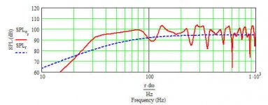
here is an example that claims to do both, the site is german and no plans are shown, but it looks very much like a BIB.
He writes that he uses two Helmholzresonators to flatten the response. One Helmholtzresonator to fill the dip around 150 Hz (I guess that's the one we see at the horn mouth), and a Helmholtzabsorber tuned to take away a peak around 250 Hz.
click
I didn't investigate any further, but to me it seems possible. If I remember correctly there was a hybrid Horn/BR design from Fostex that also pushed the bass output successfully?!?
best, LC
But in each case the filter is actually removing part of the energy being radiated ny the back of the driver. At the frequency of the dip the fiter would remove backwave energy that is out of phase, at the frequwncy of the peak it is removing in phase energy.
Keep in mind that when looking at a FR chart, you are seeing front & rear radiation. Ripple is caused by backwave phase changing with frequency and cycling thru reforcement & cancellation of the front wave. The helmholtz filters are only affecting the backwave. To flatten overall FR you remove selected frequencies from the backwave.
dave
Hi Lovechild!
This Flo 13 was what started this discussion and he claims for sure, that the reflex chamber add at 150Hz.
But if I understand what Dave has written correctly, if a vent is added, you boost the frequence at the desired place.
Something must happen with the rear wave which coming through the horn. Good ol' Newton laughin in heaven.
Correct me if I'm wrong.
Cheers
Peter
- Home
- Loudspeakers
- Full Range
- Terry Cain's BIB -why does it work and does anyone have those Fostex Craft Handbooks?