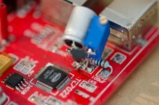
I see the SPDIF IN near the TE7022L ( pin 33 ? )
Would like to know How to function this?
AFAIK the SPDIF-IN is disabled in the firmware of the X2.
An externally hosted image should be here but it was not working when we last tested it.
An externally hosted image should be here but it was not working when we last tested it.
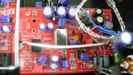
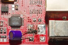
DIP14 socked with additional RF choke and decoupling cap.
Oliver,
Do the choke and capacitor come with the XO when you order from Tentlabs
or, did you get them separately?
Ned
Thanks you very much OliverAFAIK the SPDIF-IN is disabled in the firmware of the X2.
Just Received advised from teradac like this,So we hope the X2 will be the spdif receiver funtion.
And the data sheet of TE7022L rev20 show
"spdif in to USB"
But ... I hope the I2S out will be function.
Will try this week.
Subject: Re: X2
Hi Wat,
The pin 33 of TE7022L is a input for SPDIF. You can connect the standard SPDIF input to the pin. We don’t disable the SPDIF-input function, so you can try it yourself.
Michael,
Last edited:
An externally hosted image should be here but it was not working when we last tested it.An externally hosted image should be here but it was not working when we last tested it.
DIP14 socked with additional RF choke and decoupling cap.
Oliver,
Do the choke and capacitor come with the XO when you order from Tentlabs
or, did you get them separately?
Ned
Hi Ned,
AFAIK the XO comes solo. I had ordered the XO from the German Tentlabs Dealer.
He sells a accessories kit (IC-socket, cap & choke) for € 4,95.
Best,
Oliver
Hi to all
Nice work!
I too want mod my terra link x2 with:
clock gen. mod, and power supply mod,
i have built a 5V and a 3.3V voltage regulator for my terralink,
But i have a question.:
I need to use an usb isolator?, or i can use the moded terra link without the isolator and the external power supply.
So can cause something problem the external regulated voltage in my computer if i don't use usb isolator.
Thanks for your answer.
Sorry my poor english.
Bence
From Hungary
I need to use an usb isolator?, or i can use the moded terra link without the isolator and the external power supply.
So can cause something problem the external regulated voltage in my computer if i don't use usb isolator.
The USB isolator is optional. Its recommended since it removes the noise coming from the computer. I have used it also with the Teralink X2 and notice that the soundstage got wider and the base a little deeper. I also use this 12V SLA battery on the isolator:
Portable 12V li-ion Rechargeable Battery Pack 9800mAh | eBay
and its working good so far. Am thinking of doing the mods that Oliver outlined in this thread. But since I don't have any shunt regs on hand would probably try the +3.3V and +5V ones from Tentlabs. Only trouble is that I doubt they both would be able to fit in the case.
Hi,
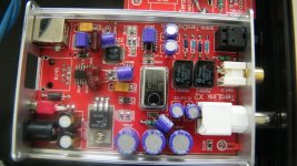
I have modded my X2 so I thought I'd share the details.
I built a usb isolator from Circuits at Home
USB Isolator. « Circuits@Home
and a 5V Sigma11 regulator from AMB using all Black Gate cap etc and a max6250 voltage reference
The σ11 Regulated Power Supply
so the s11 can power the usb isolator and X2.
I removed the clock and fed in the signal from an ocxo with its own psu. I also removed the 3.3V reg and used a potential divider into the base of a pass transistor (bc550) / capacitance multiplier to drop the 5V to 3.3V, remove noise, etc.
I'm using the asio driver with Win7 and Foobar to play flac files. The Pc is low latency
DPC Latency Checker
Overall the results have far exceeded my expectations and I now prefer this to the Onkyo soundcard, QLS QA-550 sd card player and my upsampling cd player (all of which have been upgraded too).
The X2 has a lot of potential !
I have modded my X2 so I thought I'd share the details.
I built a usb isolator from Circuits at Home
USB Isolator. « Circuits@Home
and a 5V Sigma11 regulator from AMB using all Black Gate cap etc and a max6250 voltage reference
The σ11 Regulated Power Supply
so the s11 can power the usb isolator and X2.
I removed the clock and fed in the signal from an ocxo with its own psu. I also removed the 3.3V reg and used a potential divider into the base of a pass transistor (bc550) / capacitance multiplier to drop the 5V to 3.3V, remove noise, etc.
An externally hosted image should be here but it was not working when we last tested it.
I'm using the asio driver with Win7 and Foobar to play flac files. The Pc is low latency
DPC Latency Checker
Overall the results have far exceeded my expectations and I now prefer this to the Onkyo soundcard, QLS QA-550 sd card player and my upsampling cd player (all of which have been upgraded too).
The X2 has a lot of potential !
Last edited:
I forgot to mention I also upgraded the 74hc125 to a vhc, as others have done.
The only other possible IC upgrade is the other line driver - 26c31 - but I haven't bothered to look into this.
I've tried some different caps but I get gains in one area for losses in another so I'm happy to leave them as is.
The only other possible IC upgrade is the other line driver - 26c31 - but I haven't bothered to look into this.
I've tried some different caps but I get gains in one area for losses in another so I'm happy to leave them as is.
An externally hosted image should be here but it was not working when we last tested it.
Last edited:
Hi,
I'm also playing with a Tenor based board similar to the X2, it is isolated with AduM USB isolator and fed with a Salas 5V shunt regulator, and sounds better that the stock unit this way. But I still have some clock noise that go trough the 1117 regulator to the 3.3 rail.
@KlipschKid:
Could you tell us more about your discrete regulator based on a gyrator ? I'll like to understand your shematic and try it for the 3.3V rail to see if it filters the clock noise better.
@Oliver:
Why did you choose a film cap for XO bypassing, would'nt a ceramic cap be better suited for bypassing the ripple associated to the clock 12Mhz frequency here ?
@Oliver:
Why did you choose a film cap for XO bypassing, would'nt a ceramic cap be better suited for bypassing the ripple associated to the clock 12Mhz frequency here ?
The cap was recommended by TentLabs and came with the XO.
For Klipschkid and Oliver, are you still using the Teralink X2 ? Discover any new mod and compared to other units ?
regards
kp93300
I am still using the X2 with all my current mods. Nothing new here
")

Hi,Hi Bismuth
Have you used the i2s out of your unit ?
Search tentlab web page for info about power supply for the XO.
Yes, I tested both SPDIF and I2S outputs, I'm currently experimenting with resistor values on I2S lines between an AKM DAC.
Thank you for pointing to tentlab, If I understand correctly KlipschKid used what is more a "ripple eater" than a "regulator" since R divider output voltage is directly proportional to input voltage ?
I think I have a BC547 laying around, I'll try it...
For my board, the lowest noise observed was by separating the clock rail with its own regulator.
Did anyone found the TENOR chip datasheet somewhere ?
Also, did anyone tried low noise resistors around the TENOR 3,3 and 1,8V rails ?
Thx,
Hi,
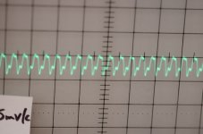
I tried the divider/gyrator ! Voltage was stable, but I got much more ripple than with the AM1117 stock regulator (see pics).
Since I destroyed the 1117 reg while desoldering I replaced it with an ADP151, ripple is now way lower than with 1117, but it needed a 100uF npo smd cap on its output to be stable.
ADP151 is very small and pinout not very easy to adapt for this board...
I also noticed some differences between my terradak X2 board and previous pictures from this thread: two missing resistors and smaller Oscons. Did anyone know what are this resistors for ?
Attachments
Hello all,
Sorry for the slow reply.
The potential divider/cap multiplier is copied from Tent labs circuit to drive clocks. You should be able to get into low uV noise or lower, not mV. It works as a low pass filter into the base of the bc550 so if there is very little noise in your your source psu, there'll be next to nothing passed through. maybe that is oscillating or you are pciking up noise from elsewhere ? I use an external clock (ocxo) with a fully independent psu and I think this helps too.
I'd like to try more usb gear but sadly, no time...
Hey Bismuth,
Just took a look at your photos. You might want to read the datasheet for the adp - it says you need equal capacitance (both low esr) both sides of the reg.
For the potential divider/cap multiplier, I used a carbon variable resistor at first, but of course, this is noiser than metal fim, so now I use 5.1K and 22K metal fim res as the potential divider into the bc550, with a 100uF low esr cap across the 22k. This gives just under 3.3V from a 5V source, and well within the tolerances for most xo.
If you do the math for the low pass filter then the cap equals 5.1K at 0.3Hz (then do some more math for the equivalent potential divider) and these res values still allow enough current into the base for the bc550 to work well, and not too soft a start up either.
Last edited:
Hey Bismuth,
Just took a look at your photos. You might want to read the datasheet for the adp - it says you need equal capacitance (both low esr) both sides of the reg.
For the potential divider/cap multiplier, I used a carbon variable resistor at first, but of course, this is noiser than metal fim, so now I use 5.1K and 22K metal fim res as the potential divider into the bc550, with a 100uF low esr cap across the 22k. This gives just under 3.3V from a 5V source, and well within the tolerances for most xo.
If you do the math for the low pass filter then the cap equals 5.1K at 0.3Hz (then do some more math for the equivalent potential divider) and these res values still allow enough current into the base for the bc550 to work well, and not too soft a start up either.
Hi KlipschKid,
Thank you, I'll try the adp with symetrical cap value as per datasheet recommendation too.
My gyrator test was with a BC547, a 3k SMD / 2.2k trimmer divider and a 330uF low esr (for an LPF fc around 0,2Hz). But I did not keep the 100uF tant after the gyrator, maybe this is the explanation for the high ripple I saw...
I do not have the means to measure sub mV ripple. Are you using a scope for that ?
Hi,
Do you mean 2.2K or 22K ? What is your input voltage ?
The scope plot is a clean waveform so that doesn't look like noise ( which usually looks like fuzzy blur ) so that's why I thought something might be oscillating or you have interference from wifi, phone signals, PC, etc. What freq is that waveform appearing at ? Are you using a usb isolator ?
My scope only goes down to 1mV so any less than that and I'm testing with my ears - sound imagery/space and the decay on cymbals, guitar strings, chimes.... but I'm hoping to get around to building Tangent's LNMP
Low Noise Measurement Preamplifier
In the meantime, my ears are reliable enough to know if I've improved a circuit or not.
- Status
- This old topic is closed. If you want to reopen this topic, contact a moderator using the "Report Post" button.
- Home
- Source & Line
- Digital Source
- Teralink X2 clock mod. with Tentlabs XO