Capasitors can hold charge for a long period of time, this is a very real danger. The higher the voltage, the higher is the degree of leathality - note, it quite easy to store enough energy in a 450v capasitor to stop your heart, even 100V dc has been know to kill ...
PS quite probably, the CRT final anode is polarised up to 10-15KV
best advice
(1) get someone else to fix it
(2) give it 5 mins after switch off and THEN check the PSU caps with a multimeter (discharge them with a resistor if nessessary)
PS quite probably, the CRT final anode is polarised up to 10-15KV
best advice
(1) get someone else to fix it
(2) give it 5 mins after switch off and THEN check the PSU caps with a multimeter (discharge them with a resistor if nessessary)
Thanks for the safety tips. The only way I am going to get better at this stuff is to do it myself so we are off..........................I removed the cap and was able to find a direct replacement online so I will be able to fix this soon. After that I will be able to diagnose any other problems.
It sounds like the resistor is a great idea! Any particular configuration?
Just so I make sure I do not have any other bad filter caps in the PS, could someone be so kind as to tell me, very specifically, how I should be using the DMM. Do I have to match my positive probe to positive on the cap? And...........there are four pins on these caps, which is which if I don't have the schematic in yet?
Cheers
with a DMM, you want to first check for any residual voltage across the cap. if it's less than 1 volt, proceed to measuring the resistance across the cap (if there's more than 1 volt, discharge the cap). you will start out when you first attach the meter probes with a very low resistance reading. this number should climb until the meter reads open circuit (depending on the meter, usually shows "OL" on the display or all flashing zeros or flashing 1999). sometimes it will start at a low (usually reads as negative when it does this) value, cross through zero and begin climbing again. since you had a pop-top cap, i would check the diodes in the circuit the cap was in, one of them may be shorted (which can do that to a cap).
usually with a cap with 4 terminals, one of the terminals is ground, and the other 3 are separate caps within the can sharing the common ground. you check them in the same way.
when you check diodes, first make sure the meter has a diode test setting (shows a symbol like this -|>|- ). if it doesn't, it may not produce enough voltage to forward bias a diode. to test a diode, put the red meter lead on the end with the stripe, and the black one on the other end, it should read open circuit. reverse the meter leads and it should read somewhere between 0.250 and 0.900 (depending on the diode type). since there are caps in the circuit, you may start out with low values showing that climb to normal (if that happens, you want to hold the meter leads in place and verify that it does climb to normal and level off).
so this is what you're looking for :
black -|>|- red open circuit
red -|>|- black 0.250-0.900
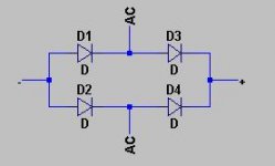
OK so my bridge rectifiers, like most I am sure, are the four pin type and they are mounted all very close to the board. I have access to the bottom for testing though. The 2 outside pins are marked + & - and the 2 center ones are marked AC. It is my understanding that these bridges contain 4 diodes each. How does one test a unit like this?
I don't want to replace all the filter caps and have one go bad again due to some other short or malfunction. Thanks again for all the help.
Cheers
I don't want to replace all the filter caps and have one go bad again due to some other short or malfunction. Thanks again for all the help.
Cheers
OK ,
The bridge, CR1412, seems to check out at 0.532ohms at all 4 points. So I should be good to go there right? Or is there a possibility that one of the other bridges could have caused the problem. Or................... did we already say that it could just be due to old age?
Cheers
The bridge, CR1412, seems to check out at 0.532ohms at all 4 points. So I should be good to go there right? Or is there a possibility that one of the other bridges could have caused the problem. Or................... did we already say that it could just be due to old age?
Cheers
Note:
you will need to disconnect the bridge to check it, now check each diode in each direction. as unclejed describes, it SHOULD read open circuit in one direction and a lowish value in the other direction.
its well worth being methodical as this point, as there is nothing worse that seeing your expensive new components going up in smoke and nothing better than the moment you power up and that expensive door stop turns into a usefull piece of equipment
I will have to check it when I get home from work. I put my DMM in the diode check mode and got a reading of 0.532'ish at all of the four pins with the black probe on the striped side of the diodes and open with the probes reversed. But again, I will recheck when I get home.
Cheers
Cheers
I will have to check it when I get home from work. I put my DMM in the diode check mode and got a reading of 0.532'ish at all of the four pins with the black probe on the striped side of the diodes and open with the probes reversed. But again, I will recheck when I get home.
yup, that sounds right. i would replace the blown cap and go for a power up. assuming the fuses stay intact, keep an eye (or should that be nose) open for any bad smells / smoke.
good luck !!
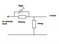
obviously they need to be BNC, but the input impedance of the scope is 1 MEG. so it doesn't really matter what you use for cables, etc.... one thing i learned is that if you connect to a dummy load and attempt to make your own 10:1 attenuator, it sould be a 1 meg resistor across the scope input, and a 10 meg resistor between the input hot and the dummy load hot. you should also have a 50pf trimmer cap across the 10 meg so you can adjust the frequency compensation. otherwise when an amp clips you will not see flat-topped waves, but the tops will be at an angle.
Attachments
there are a couple of things that could cause this :
(1) the bridge / diodes may have tested OK with your meter but could still be leaking at higher voltages. i don't think this is so likely as the cap would probably fail very quickly ...
(2) the new capasitor is leaky - this is a possiblity. If you have a bench PSU of the right voltage you can test the leakage current by connecting the cap up with a series resistor and measure voltage drop (say, 1K which will give 1V per milliamp of leakage)
(3) the new capasitor does not have a high enough ripple current rating. what type of cap did you use ? what information do you have on the original ? The ripple current rating could also be exceeded by some down stream fault pulling too much power from the power supply. Do you have any info on the expected load current ?
BTW, did the scope actually work for the 45 mins ?
- Status
- This old topic is closed. If you want to reopen this topic, contact a moderator using the "Report Post" button.
- Home
- Amplifiers
- Solid State
- Tektronix 475 PSU Troubleshooting..........