Hi sfc1000,
Wow, you're asking for an entire course!
I haven't read that manual in years, but unless you are told otherwise, the common (gnd) on the scope lead goes to the closest ground terminal to he test point. Put the scope in DC mode, 0.5mS/div for horizontal and range down on the DC scale until you can see the average DC level. Adjust the "fuzz" until the ground reference is centered. Note that it is assumed you have shorted your scope lead on that range to set the zero point on the centre of the screen.
You probably need a test filter for the gain adjustment and use a lissajous pattern (X-Y) and adjust for a circle. This is only valid for the test disc specified. I use a vastly different method that is correct for gains, and much closer for E-F balance. This uses a special test disc and requires training and experience.
Adjusting a CD player is not a job for a beginner. This will, without training, frustrate you and you may get the CD player into a state where it does not play. One word of advice. The CD player worked fine with the alignment it had, and it doesn't drift much at all. You are better off not touching the alignment! If the machine has problems, chances are the alignment is not the issue. Fix the problem first!
Check the laser diode efficiency and height of the eye pattern before you do anything. You are allowed a 10% rise in laser current before the head is well and truly worn out. If you attempt to increase the laser current, you may reach a point where it stops working. If that happens, you killed it forever. If the RF pattern is low, the head may be done as well. You are wasting your time trying to get a CD player working with a weak head.
Check for vibration if the head checks okay. For a CD player to stop working properly, something happened. It has servos, so it can wear slowly over time and stop working once the wear is beyond the range of servos to correct the problem. So a sudden failure could be just accumulated wear over many years.
Messing with the alignment is absolutely the very last thing you do, and that is after you correct the actual problem.
-Chris
Thanks Chris.
I've set up the test bench today while not having the YESDS-18 Sony test cd that is required. Apart from the special made errors, is it absolutely needed? Tones, strength in signal?
While driving say a 1,7kHz tone from the audio generator via the scope to the test pin, I get that signal very clean. I surveyed the signal from my old Leader LAG-27 audio generator with my Fluke 179, with regards to Volt 4,0 Volt peak to peak, and the frequency 1,7 kHz. Both were dead on all the time. and the scope on ch1 showing a very clean signal.
I think I got the point of the single wire I was in doubt about, from ch2 on the scope to the cd servo board, or rather the other way round, tp1, pin 2 or 4, depending on looking at focus gain or tracking gain respectively, as I think the wire is a signal return from the player to input on ch 2 on the scope to show it on the display and align that with 90° to the audiosignal generator signal, and since there is a common ground, there is no gnd wire to that, as the gnd is shared on the scope, the generator and so on. Is that correct?
And interpreting those 90°, is that two sinus curves that is supposed to be 1/4 (90°) moved away from each other? Is that the correct representation? I don't know if I made it clear, as English is not my native language. Sorry, if it's a bit unclear. I'll try again: I see two sinus curved. One above the other, say ch1 is the generated tone, and below is ch2 with the return signal from the player, and that sinus curve is moved slightly to the left compared to the above. As I think a full sinus curve is 360°, 90 must be a 1/4 of that. The problem I had there, is not in adjusting Focus Gain, but in Adjusting Tracking Gain. There, the return signal from the cd-player, was weak and "think" - hard to read, and adjusting the trimmer did not move it left/right, but made it slightly glatter or higher, so to speak. Could be the cd I was playing, not being the correct YEDS-18 ...
So, without using te YEDS-18 test cd, I just played a normal music cd (not a home burnt one), and my signal is "flatter", not showing the same high amplitude. Is that because the output from the recording is lower, as I noticed that the YEDS-18 signal is maxed to 0db, hence giving me a flatter sinus curve?
It may be, that Sony made a very high output signal on the cd, therefore requiring Teac to demand 4,000 (as in 4 point zero, not 4000...) Volt from the signal generator to have same balance? (or signal strength)
(I will experiment with that tomorrow, by adjusting the voltage on the tone generator down to say3,000 Volt or less).
Despite being a reasonably affordable low end digital scope, I get a somewhat readable eye pattern. I adjusted the persistence time down to slower, and got a clearer reading. There were still some small distortion and a bit bouncing and could be clearer, so I tried adjusting Focus balance to get is larger and clearer. It changed a little bit, but still had distortion. So I tried moving about some cables in the cd-player, and it helped a bit, particularly the multicable from servo board to dac/analog out board.
To other moving about with any other cable improved it further. So no change moving the flat ribbon cable from the laser nor any sensor/switch cable.
Anyway, I adjusted as procedure and got the player a bit better. But still having trouble reading toc or playing. Not all the time, but say half. I thing that the servos are not supposed to be making a noise, so I noted when they stopped that, and it is about the correct adjustment trimming.
I have checked the laser current to be 1,04 Volt over R407 and divided that with 22 and multiplied that with 1000 and got 47,3mA. Printed on it's label is 47,0 mA. And Sony allows 10mA on top being 57 mA, so I think it is 3% worn (I know it hasn't seen much use ever). So plenty of theoretical hours left, unless something else shows up, of course.
I should mention, that this whole VRDS-10 cmk-3,2 drive and the VRDS-10 servo board is shoehorned into one of my Copland CDA-288 Mk. II SE players. Hence there could be other problems. I modified the servo board to avoid a filter of some sort just before the multi connector towards the dac/analogue output board, thereby avoiding near al of the noise I heard while not having done the mod yet to the new VRDS-10 servo board. Therefore the whole laser mec and magnetic rails have been out and about. I did take care in trying to avoid static damage. I cannot say however, if something happened anyhow. I can say that another kss-151a and it's flex cable etc, have been installed, but same result.
It was not really possible for me to get a usable reading for the tracking balance adjustment, which is one of the first parameters to work on, when setting it up according to the service manual.
Instead of getting a curve read out as per manual, I got a big quickly sweeping zig zag noisy picture. That is hard to adjust form. Any ideas as to another way of looking at it on the scope or something else?
While building the drive into the cda-288, I cleaned everything and lubed where needed. Laser slides totally free and easy. Not scratches or dust or layer of film on the laser.
I will not raise the laser current. Is that normal to do on old lasers?
Thank you for your help so far.
Kind regards,
Jacques
Hi Jacques,
Never adjust the laser current! Only hacks do that.
The point of the test disc has nothing to do with the recorded audio signal and everything to do with the pressing of the information and construction of the CD. It is not possible to burn your own, period. As I said, do not attempt to adjust the focus and tracking gain without the specific test CD and using the exact procedure. You would have been a lot further ahead with an analogue scope.
If the unit has trouble reading the TOC, you should not have touched anything. The laser current is fine, but something else is wrong. Never twiddle pots before correcting the fault. The last adjustment is one I do a different way, but with a special test CD and a lot of experience. I said that to start.
I honestly don't know what to tell you. Instead of checking a couple specific things, you went ahead and messed with the alignment. You are using a scope that isn't up to the task. Do you know what I had to buy for a DSO? A Keysight MSOX3104T, look it up. Lesser digital scopes I found were not useful, so you need to get use of an analogue scope in order to assess the eye pattern.
Watch the eye pattern while the unit attempts to read the TOC. That would give me a clue as to what is happening. I don't think you will interpret it so easily due to lack of experience. Anyway, give it a shot.
Thanks Chris.
1/: I've now gone through some of the mechanical points of my rebuilt and modded Copland CDA-288 Mk. II se cd-player. I found one bad soldering from the clock generator signal in, that had become somewhat semi-loose (loose) and resoldered it. That must have given a very unstable clock signal, and hence all sorts of trouble. Now, it plays much more stabe (when actually playing) and I cannot any longer detect a slight tick in the speakers once in a while. I have to do much more listening on that.
I have a question: I would like to experiment with different clock generators later on. So, in trying to aid that, will it be an idea to solder in two stays instead of the wires directly, as they are now, from the external clock, and then use two small connectors, say a pc connectors fitting the dimensions, or is that asking for more trouble (I mean the connections)?
2/: I will get a laser meter to check the output.
3/: No, I will NOT ever touch the laser current!
4/: You mentioned vibrations. Would that be vibrations i the disc once spinning? And/or vibrations in the VRDS platter and/or shaft? I have some extra players to experiment with and see how they spin. I will speak to a friend who is a mechanic with fine works on our technical university, and see, if he can measure the eccentricity and wobble (so in the horizontal plane and vertical plane).
I will also ask him (he is also a watch mechanic) to try and measure the wear and running of the spindle/platter shaft.
Next, I will look at the top adjustment on top of the platter/spindle axle, and look at how much this is tightened. I can measure very fine tolerances in tightening and loosening.
I think I read somewhere here, that this tightening alters the height between the disc and the laser, hence changes focuspoint etc.
Any suggestions to that?
5/: I am currently looking at an analogue scope: Hitachi v-1565 100Mhz 2 channel scope. I is a relatively new one and have more functions than the basic ones. I can get it from an electronics engineer who said it is a good quality scope. He have done many cd-players and used this one, but is now retiring.
Is that in your view a fairly good scope?
6/: I also calibrated all 4 probes I have for the digiscope I have now, and tried all 4 channels and the following point 7 and 8 below, are done with all compositions of that. same results. I think they are either all equally out or the all work fairly okay. I will try to get two high quality probes.
Every second year I have my Fluke 179 looked over and calibrated, like some of my other tools, but I did not have my first scope (Rigol DS1104z Plus, with all software options set open) calibrated. The man I bought it from did not have that done either, and found it to be fairly accurate. It is though, still a digiscope and more over not a super expensive one, as you mentioned.
7/:Focus balance:
Now, if I set the probe to 1:x, calibrated, and persist time to minimum, dc coupling etc, I have a perfect diamond RF pattern. I then adjusted that to be maximum height. It's also now balanced between lower and upper part. I played a little bit forth and back and also changed discs a few times. Same result.
8/:Focus offset check. I then measured the voltage for focus offset, and it should be below 50 mV. I measured 30,2 mV, changed discs, turned off and on etc, and got the same result every time.
I then measured the focus offset voltage on my other (standard) Copland CDA-288 cd-player, and it is near the same at 29,9 mV and that player works perfectly. Never touched any pot or any adjustments in that machine since new.
9/: I did a re-measuring of the laser in my cd-player that I am working on (the CDA-288 Mk. II se with VRDS-10 cmk-3,2 drive and another bridge and platter in (see later) modding etc.) and I found it to be the exact same value as some days ago. I then measured the other VRDS-10 I have and that is nearly the same value, actually a bit more wear so to speak.
10/: While rebuilding the CDA-288 Mk. II se, I have amongst other things, changed the VRDS bridge and platter, to a VRDS-Super model (from Teac P-70 and I think it's also in Wadia 861SE).
I therefore assume, that the height might be slightly different. Before touching pots, I swapped back to the normal cmk-3,2 bridge and platter, and the machine plays well.
But I want to use the P70 bridge and platter, so it would be very good to know how to measure or other things to look for.
Any comments on that?
Phew, that was a lot, so I will describe my findings on Focus Gain and Tracking Gain later, as I redo it.
A YEDS-18 is on the way.
I really appreciate the time and effort and experience you have and that you gave it some time to comment and advice.
Kind regards,
Jacques
Edit: Thinking about it, I think you are right. There must be some mechanical misalignment between the platter/disc and the laser. When I load a cd and press either "Close" (to read toc) or "Play", I get some inconsistency in doing that. It will either reject the cd after trying, or play. The frequency is right now gone from 50/50, to 40/60. It's getting closer, but that is other variables, such as laser adjustment. So, is that what is called "disc table height"? Apart from 20 odd years of playing/staying, there must be a difference in that height, because of my new VRDS-Super bridge and platter.
I would really like to get some sort of reference as to what it should be, and measure and adjust.
Last edited:
Add-on: I can still detect a slight click in the speakers, but far more rarely.
Could the clicks be a combination of say bad connections, unstable clock signal, and wrong laser to platter/disc height, laser adjustment needed etc?
Also, I think there is a point here, as the only cd, I've had real trouble playing, with lots of clicks and distortion very audible, will now play from start to half and then begin to have trouble FF or playing with distortion. It's a produced cd, nut a home burnt one, but I bought it from a monk i Georgia in eastern Europe and it's the absolute only place to buy it directly. Plays perfectly on my other cd-players. Platter height, laser adjustment?
Kind regards,
Jacques
Last edited:
Hi Jacques,
Sorry I don't have more time, but here are some answers for you.
1.) That will definitely help
2.) Please do not waste your money. I was forced to buy one when CD players first came out
3.) Fantastic!
4.) Don't touch more than you have to. See if there are vibrations from any bearings.
5.) Yes, that seems like a very good choice! Perfect!
6a.) Good probes are expensive, and only available as X10. You need one good probe.
6b.) I used to calibrate and certify equipment. Primarily your use of a scope will be to look at wave forms. Don't worry about calibrating it.
7.) The eye pattern requires a X10 probe
8.) Focus offset is ideally zero using a scope. Noise makes using a DVM impossible
9.) That value will vary between laser heads. Don't expect the values to be the same.
10.) All I can suggest is to read the manual. Changing the parts probably doesn't help
Keep in mind that you want the spinning mass to be as low as possible. This is not a record player and extra mass is your sworn enemy. The entire concept of the VRDS and Pioneer stable platter is severely flawed. The CEC belt drive concept is even more stupid. The CD must be able to change rotational speed quickly. High rotating mass actually fights you on this. It is a very stupid idea.
I found the Teac transports to be far too complicated and prone to problems. I did warranty on these. The simple magnetic clamp as found in Sony transports is really the best way to go, sorry to say.
-Chris
Hi Jacques,
The clicks are digital errors where the DSP mutes entirely. That means huge series of digital errors normally caused by scratches or gouges. Nothing more complicated than that.
Clock errors cause other issues and would be extremely rare. Of course, mechanical alignment can make this worse. Mechanical alignment is done first, it is the critical basic procedure. Electronic alignment then becomes easier and he servos do not have to correct as much. The very best transport in this regard ist he one used in the Nakamichi OMS-5/7.
-Chris
Thank you for your reply, Chris.
The clicks being a result of long strings of errors forcing the dsp to mute, is a bit strange to me, if it's caused by scratches, holes or long scratches. I'll read up on the matter. Sounds interesting.
When I play any cd, there are a few small clicks in the speakers, while the music plays. It does not stop or anything like that.
I have detected some wobble in the heavy VRDS platter and axle. I now will look closer at the bearings/bushes. I think there is a bronze one.
I also have a Esoteric P2s drive that I will take a look at and measure for excessive play anywhere.
I need to find the table height for a VRDS-10 with kss-151a laser.
I adjusted focus gain and focus tracking gain to be near the other VRDS-10 and went on from there. It now plays much better, It accepts any cd incl. HDCD I've tried so far and plays them - no skipping etc. I can also now >> and << with no hick ups except 2 cd's. None, I mean absolutely none of my over 800 cd's have any scratches that I can detect with a good light source and my eyes. There may be other errors of course.
It will not play any burnt cd. It used to be able, but not now.
I'll leave it for now and only work on the platter mec and it's axle, and wait till' I have a better scope, better test probes and the YEDS-18 for any further examination and adjustment.
Thanks a lot for your help so far")
Kind regards,
Jacques
The clicks being a result of long strings of errors forcing the dsp to mute, is a bit strange to me, if it's caused by scratches, holes or long scratches. I'll read up on the matter. Sounds interesting.
When I play any cd, there are a few small clicks in the speakers, while the music plays. It does not stop or anything like that.
I have detected some wobble in the heavy VRDS platter and axle. I now will look closer at the bearings/bushes. I think there is a bronze one.
I also have a Esoteric P2s drive that I will take a look at and measure for excessive play anywhere.
I need to find the table height for a VRDS-10 with kss-151a laser.
I adjusted focus gain and focus tracking gain to be near the other VRDS-10 and went on from there. It now plays much better, It accepts any cd incl. HDCD I've tried so far and plays them - no skipping etc. I can also now >> and << with no hick ups except 2 cd's. None, I mean absolutely none of my over 800 cd's have any scratches that I can detect with a good light source and my eyes. There may be other errors of course.
It will not play any burnt cd. It used to be able, but not now.
I'll leave it for now and only work on the platter mec and it's axle, and wait till' I have a better scope, better test probes and the YEDS-18 for any further examination and adjustment.
Thanks a lot for your help so far
Kind regards,
Jacques
Last edited:
Hi Jacques,
Great! Good luck.
The CD doesn't stop. The clicks are abrupt changes in the audio signal most often caused by digital zero (mute) being inserted. This occurs when the data is so corrupt that interpolation or repeating data is not possible. Data errors causing an abrupt change in the analogue level can also cause this. With some CD players, there are error flags called C1 and C2. C2 is an unrecoverable error. You can see it on a scope, your digital one could freeze the event (it is a digital level) normally synced to the word clock. So some activity on C1 is normal. Activity on C2 is a great deal more severe and should be sporadic at the worst in a normal CD player with a good CD.
CDs have a BLER rate, even a perfect one. BLock Error Rate. The flags still exist, or did, but are buried in the chip and do not have accessible pins to monitor. They are used for internal processing. DAT machines also have the same flags - no surprise. We would monitor those to fine adjust the tape path.
-Chris
Hello Chris,
Thanks for the explanation. Since I modified the VRDS-10 servo board by copying the 4 jumper wires inserted on the cmk-4,0 servo board by Copland, aka I did the same on the VRDS-10 cmk-3,2 servoboard which is to some extent a similar design, I managed to bring down the clicks from very many, to few, and after adjusting the servos, to very few, I will look at the servo board again and see what's going on - what is happening to the signal before being sent by cable to the dacs/output pcb.
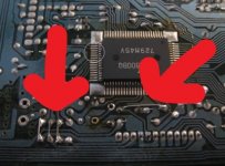
The removed components are a trimmer, a small capacitor and the old crystal, and instead a LClock XO with separate power supply is used. The long row of solder points in the bottom is the output connector to the dacs/output stage pcb mentioned.
If I can find a way to look at that data error level, I'll do it on both this modded cda-288 with vrds-10 drive and servo pcb and my standard cda-288, with it's cmk-4,0 drive and teac servo board, which may or may not (don't know yet, be a vrds-7 servo board. I happen too have a vrds-10 also, so I'll open that and compare the servo pcb's for starters.
On another note: Since I did a few adjustments last night, being in the state it is now, I noticed, that the point of adjustment on Focus Gain and Tracking Gain, made the servos just stop being noisy. They are silent now.
Your input is greatly appreciated. Thanks.
Kind regards,
Jacques
Thanks for the explanation. Since I modified the VRDS-10 servo board by copying the 4 jumper wires inserted on the cmk-4,0 servo board by Copland, aka I did the same on the VRDS-10 cmk-3,2 servoboard which is to some extent a similar design, I managed to bring down the clicks from very many, to few, and after adjusting the servos, to very few, I will look at the servo board again and see what's going on - what is happening to the signal before being sent by cable to the dacs/output pcb.
The removed components are a trimmer, a small capacitor and the old crystal, and instead a LClock XO with separate power supply is used. The long row of solder points in the bottom is the output connector to the dacs/output stage pcb mentioned.
If I can find a way to look at that data error level, I'll do it on both this modded cda-288 with vrds-10 drive and servo pcb and my standard cda-288, with it's cmk-4,0 drive and teac servo board, which may or may not (don't know yet, be a vrds-7 servo board. I happen too have a vrds-10 also, so I'll open that and compare the servo pcb's for starters.
On another note: Since I did a few adjustments last night, being in the state it is now, I noticed, that the point of adjustment on Focus Gain and Tracking Gain, made the servos just stop being noisy. They are silent now.
Your input is greatly appreciated. Thanks.
Kind regards,
Jacques
Attachments
Last edited:
All Right, so following Chris recommendations, I've acquired a fairly good old school oscilloscope and went through the adjusting processes again. Twiddling with those a few times, backing up and down a bit from the best point I could find, I've noticed that the points where you want to be when adjusting is surely elsewhere on the pots adjustment range, using the analogue oscilloscope (a Hitachi V-1565) and being particularly careful with calibrating the probe and connecting gnd, I've now been playing cd's all evening, and it's very near where I want it to be. No clicks in the speakers and the soundstage have opened up and music plays with more details; fine details.
Very satisfied. I will though look at it more carefully together with an electronics friend, who do this for a living.
Thanks for the help.
Kind regards,
Jacques
Very satisfied. I will though look at it more carefully together with an electronics friend, who do this for a living.
Thanks for the help.
Kind regards,
Jacques
Hi Jacques,
I'm very happy to hear that.
There is a lesson in this in that the characteristics of your test equipment can lie to you in certain situations. The analogue scope you picked up is honest. No sampling issues and I bet the eye pattern is far easier to see clearly.
A similar thing holds true when you measure things with a meter. It pays to look at the test point with an oscilloscope to get the full story. Your meter will interpret things, and if there is an AC component it may mislead you. Every meter is different.
-Chris
Hi Chris,
Yes,, there are certainly some factors that come in play when using my digiscope, and absolutely yes, it' far more easy to see on the analogue oscilloscope. Far better to use the analogue for the eye pattern. I also discovered a bad probe, so use another one.
On my modded copland, the vrds-10 (cmk-3,2) drive runs dead silent now.
I measyred the wobble in the vrds-super platter axle to be 1mm at the outer edge, so I have asked a friend to make a new axle and a new twin bronze bearing for the platter. Do you have any experience in doing that?
Alternatively, he will try to use the platter and axle from my P2S drive, and make a bigger 6mm twin bronze bearing.
Right now, I am looking at a standard vrds-10 and my copland with vrds-10 servo and drive. The eye pattern on the standard machine is a bit smaller but a little more defined or clear.
Of course I won't touch the standard machine. It plays perfectly.
I have made two other threads with interpreting the eyepattern, with regards to size and clearness, as there are a couple of things I need to understand - well, apart from all the rest
Besides using service manual adjustment procedures, is it possible to look at the eye pattern when adjusting say focus gain or tracking gain, for size and clearness?
Kind regards,
Jacques
Last edited:
Hi Jacques,
No experience with that.
Like I said, you want minimum rotating mass. Those transports are behind the 8-ball. The actual CDs are often not true.
Anyway, not interested in providing a course on CD players. Good luck with this, you seem to have got things running.
-Chris
No experience with that.
Like I said, you want minimum rotating mass. Those transports are behind the 8-ball. The actual CDs are often not true.
Anyway, not interested in providing a course on CD players. Good luck with this, you seem to have got things running.
-Chris
Okay, so time to round off this adjustment for my part, not to hijack it too much.
I have now done a very long series of micro adjustments by analogue scope, true rms dvm, and by listening to both laser coils, the drives sound overall, also comparing to some of my other vrds-players incl. measuring on those, and listening to pieces of music that I know very well. I've changed between several cd's all the way back from 1988 and up to recently. I've also changed test probes and other wires used and experimented with the setup of wires, cd-players cables etc. to verify if there was an unknown source of disturbance (in lack of what to call it, as I am not educated in this field) and verification in general.
I have discovered a dead soldering of a clock wire, a slightly worn bearing (2 actually) which I will change later on, when my next improved platter/bridge mec is ready, together with a stiffed up upper chassis. I have also discovered a slight wobble in the platter, hence the need to correct that. And I have shimmed the drive so that the table height is as my other vrds-driven cd-players.
Meanwhile, with these many many repeated adjustments which also includes many microscopical movements of the pots (there's a big secret in there), I've now managed to make the Copland CDA-288 Mk. II s.e. with my built in cmk-3,2 drive and VRDS-Super bridge and platter, plus some Jantzen caps in the analogue output stage, together with an LClock plus it's own dedicated transformer, play all my cd's including burnt cd's. I spins up silent and accepts any cd quickly, coils are very near silent, drive is silent with no funny noises and repetitive dangs, ticks, dings or other sounds, and I finally got rid of the clicks in the speakers, and all this together have made the cd-player spin every disc and during all this, the sound have really improved a lot: much more detailed, e.g. whiskers sound very much like when we are at a concert, same goes for a grand piano, drum skin, all sorts of guitars analogue and electrical, and the sound stage have improves to be yet bigger and deeper and higher. I would say that the music is now more free from the speakers (modded B&W 802s3 on Sound Anchors). All in all a big improvement in sound.
Other gains I wanted are now also met such as glass laser, more stable drive from a mechanical standpoint, faster laser movement, floating magnet laser drive and hall motor for the platter. Plus it's easier to service this drive than the original cmk 4,0.
My big thanks to Chris who despite my many questions - one answer opens up a whole series of new questions... - gave me some very good advice, that I cannot look up in a manual or a book, for example the use of an old scope over a digital one; that anything can be seen in the eye pattern when making adjustments, look for mechanical perfection first and that many repetitive series of adjustments, micro adjustments and measurements have to be made to finetune it.
It now plays really really well and is a huge step in comparison to my other standard Copland CDA-288.
Next up are power supplies, new caps etc.
So thanks a LOT from an absolute beginner Great forum!
Okay, so finally time for some late night dinner.
Kind regards,
Jacques
I have now done a very long series of micro adjustments by analogue scope, true rms dvm, and by listening to both laser coils, the drives sound overall, also comparing to some of my other vrds-players incl. measuring on those, and listening to pieces of music that I know very well. I've changed between several cd's all the way back from 1988 and up to recently. I've also changed test probes and other wires used and experimented with the setup of wires, cd-players cables etc. to verify if there was an unknown source of disturbance (in lack of what to call it, as I am not educated in this field) and verification in general.
I have discovered a dead soldering of a clock wire, a slightly worn bearing (2 actually) which I will change later on, when my next improved platter/bridge mec is ready, together with a stiffed up upper chassis. I have also discovered a slight wobble in the platter, hence the need to correct that. And I have shimmed the drive so that the table height is as my other vrds-driven cd-players.
Meanwhile, with these many many repeated adjustments which also includes many microscopical movements of the pots (there's a big secret in there), I've now managed to make the Copland CDA-288 Mk. II s.e. with my built in cmk-3,2 drive and VRDS-Super bridge and platter, plus some Jantzen caps in the analogue output stage, together with an LClock plus it's own dedicated transformer, play all my cd's including burnt cd's. I spins up silent and accepts any cd quickly, coils are very near silent, drive is silent with no funny noises and repetitive dangs, ticks, dings or other sounds, and I finally got rid of the clicks in the speakers, and all this together have made the cd-player spin every disc and during all this, the sound have really improved a lot: much more detailed, e.g. whiskers sound very much like when we are at a concert, same goes for a grand piano, drum skin, all sorts of guitars analogue and electrical, and the sound stage have improves to be yet bigger and deeper and higher. I would say that the music is now more free from the speakers (modded B&W 802s3 on Sound Anchors). All in all a big improvement in sound.
Other gains I wanted are now also met such as glass laser, more stable drive from a mechanical standpoint, faster laser movement, floating magnet laser drive and hall motor for the platter. Plus it's easier to service this drive than the original cmk 4,0.
My big thanks to Chris who despite my many questions - one answer opens up a whole series of new questions... - gave me some very good advice, that I cannot look up in a manual or a book, for example the use of an old scope over a digital one; that anything can be seen in the eye pattern when making adjustments, look for mechanical perfection first and that many repetitive series of adjustments, micro adjustments and measurements have to be made to finetune it.
It now plays really really well and is a huge step in comparison to my other standard Copland CDA-288.
Next up are power supplies, new caps etc.
So thanks a LOT from an absolute beginner
Great forum!Okay, so finally time for some late night dinner.
Kind regards,
Jacques
Last edited:
Hi Jacques,
Yes, all you need are the basics. The rest falls into place.
Don't replace supply capacitors unless they are defective. Differences between good brands are slight at the very best. Look at the signal across the capacitor with your analogue scope. AC setting. If it's clean, no problem. Ripple is fine, sharp "pips" on the leading edge is not.
Use your common sense, that trumps every mis-guided report of improvements by capacitor swaps. In addition, more capacitance is a problem, not a solution.
-Chris
- Home
- Source & Line
- Digital Source
- Teac VRDS-10 help please?