![SDC10420 [1024x768].JPG](/community/data/attachments/198/198494-fe9a5ace3ff19edd83bb40615122f838.jpg)
![SDC10421 [1024x768].JPG](/community/data/attachments/198/198501-df95818e334b0cb47880c7a1f492b13e.jpg)
![SDC10417 [1024x768].JPG](/community/data/attachments/198/198506-ad7094292716e72fb02f754ce9b56143.jpg)
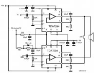
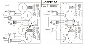
sorry to ask these question but I'm not so professional at electronics, but I still want to start with this one as Apex diagram two TDA with power supply 24v. I'm already have 2 TDA7294 and diagram from ST as pdf. when I compared them at their part they didn't use fuse for protect the chips so that why I want to use Apex instead of their diagram. as I already know safety is the first step and next is to apply instructions to make things work.
but I don't know how to build power supply for this one from the parts I have:
- 2x22vAC 80VA transformer.
- Diode bridge 15A.
- for capacitor I don't know which one should use. but I could buy anything needed.
sorry again to ask these questions, but most parts explain about this chip TDA7294 and the amp parts not the power supply and I'm so confused to start with it.
sorry to ask these question but I'm not so professional at electronics, but I still want to start with this one as Apex diagram two TDA with power supply 24v. I'm already have 2 TDA7294 and diagram from ST as pdf. when I compared them at their part they didn't use fuse for protect the chips so that why I want to use Apex instead of their diagram. as I already know safety is the first step and next is to apply instructions to make things work.
but I don't know how to build power supply for this one from the parts I have:
- 2x22vAC 80VA transformer.
- Diode bridge 15A.
- for capacitor I don't know which one should use. but I could buy anything needed.
sorry again to ask these questions, but most parts explain about this chip TDA7294 and the amp parts not the power supply and I'm so confused to start with it.
Only you need transformer and heatsink, all the rest is on the pcb (two channels and PSU), go to posts #1 and #5.
Regards
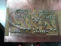
I tried your PCB with transformer mention before in post 1-5, but no voice out even when I tried both line in the out speaker silence.
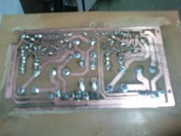
Note: I use toner for print the PCB so it flipped the direction let to right and right to left, but the parts and cap all the same as your PCB.
do I need to connect the heatsink to anything? or it just fine and I miss something else anyway I'll post some picture for them soon.
Note: I use toner for print the PCB so it flipped the direction let to right and right to left, but the parts and cap all the same as your PCB.
do I need to connect the heatsink to anything? or it just fine and I miss something else anyway I'll post some picture for them soon.
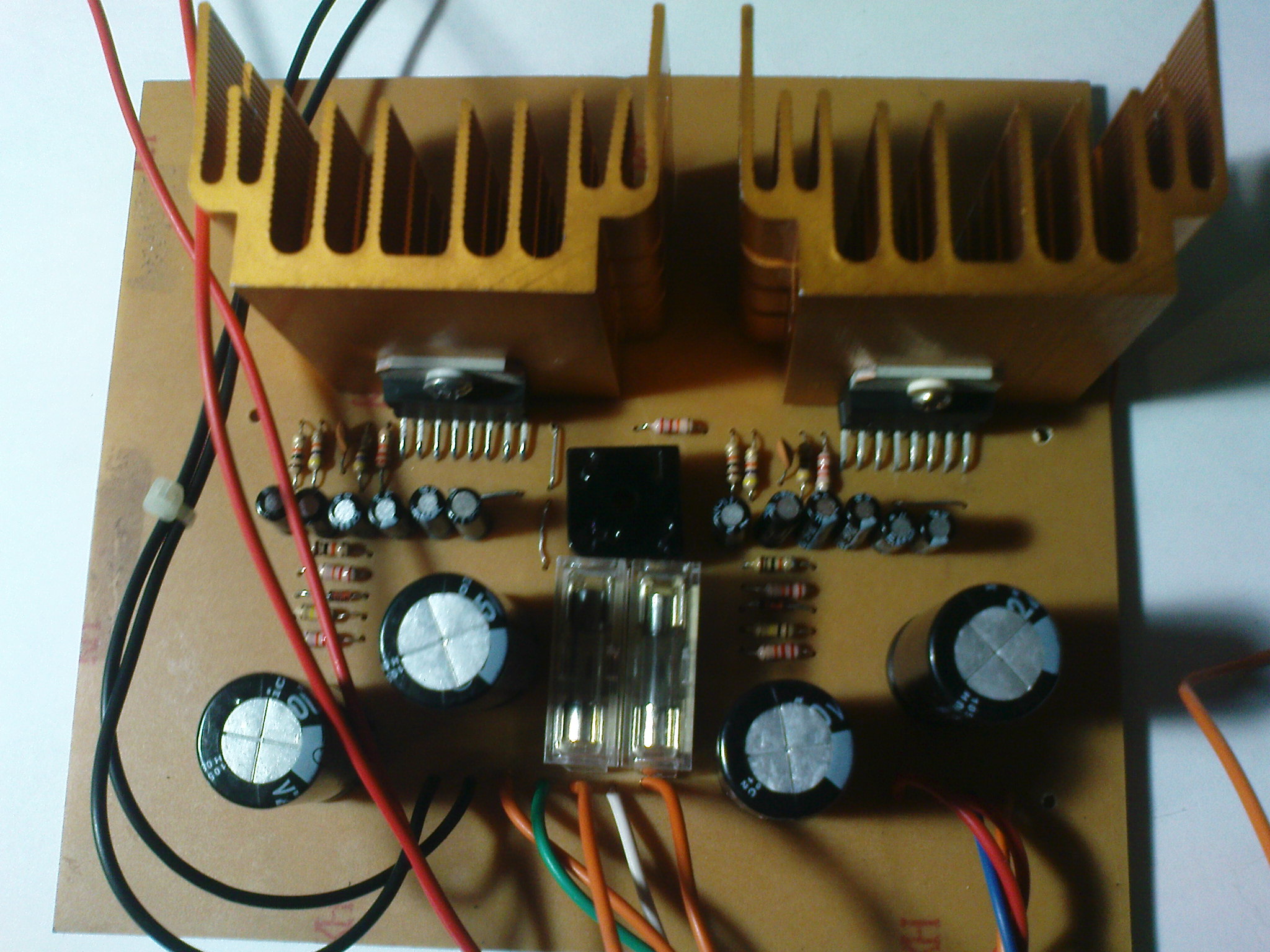
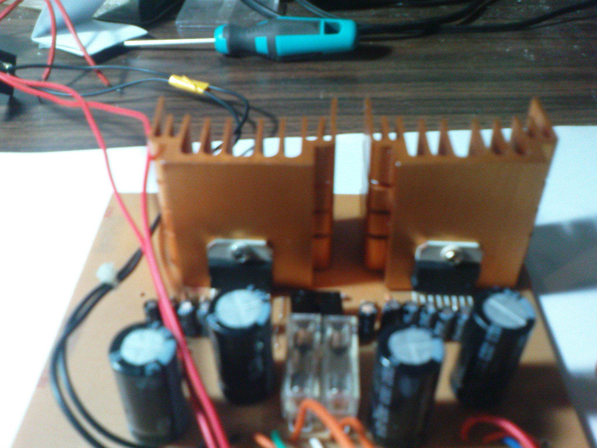
well here some pictures for what I did with everything
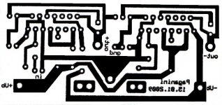
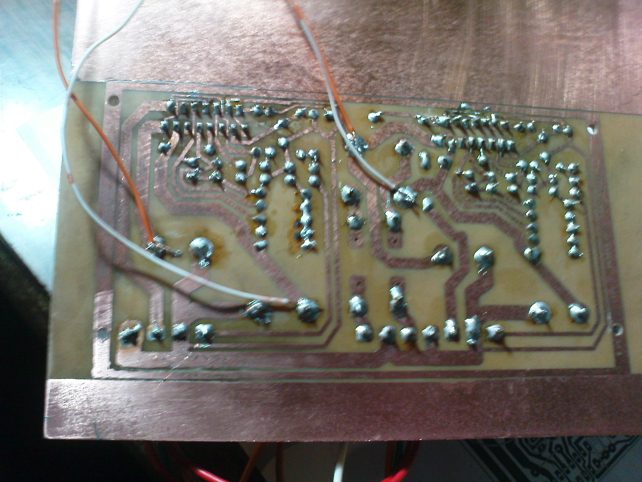
first for PCB:

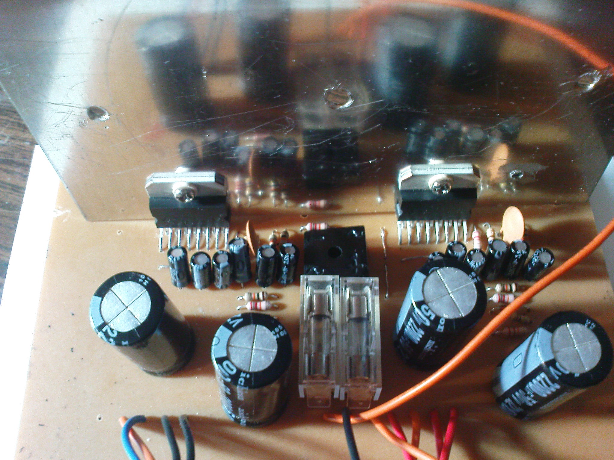
and here the over picture of components:
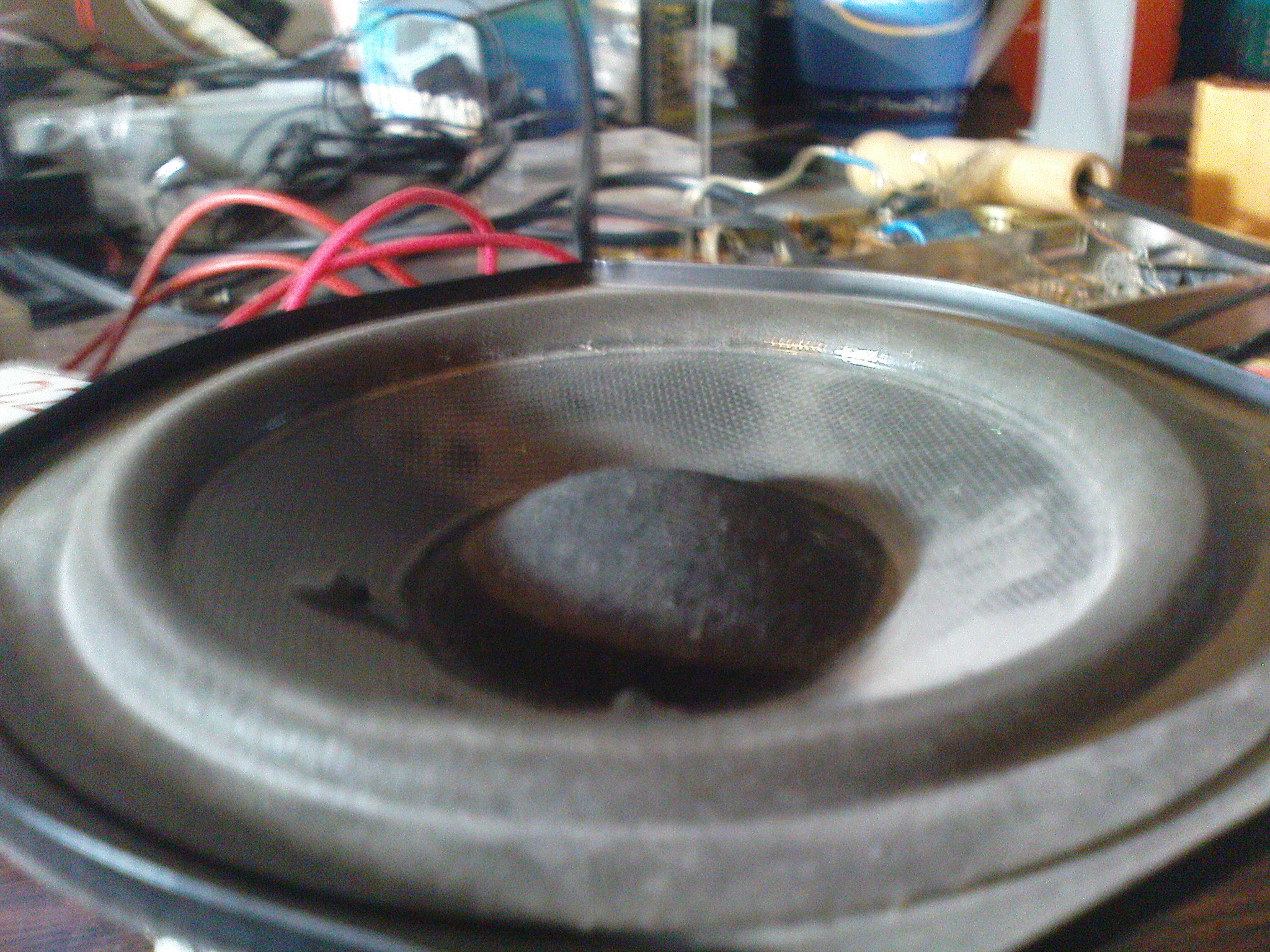
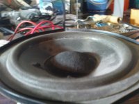
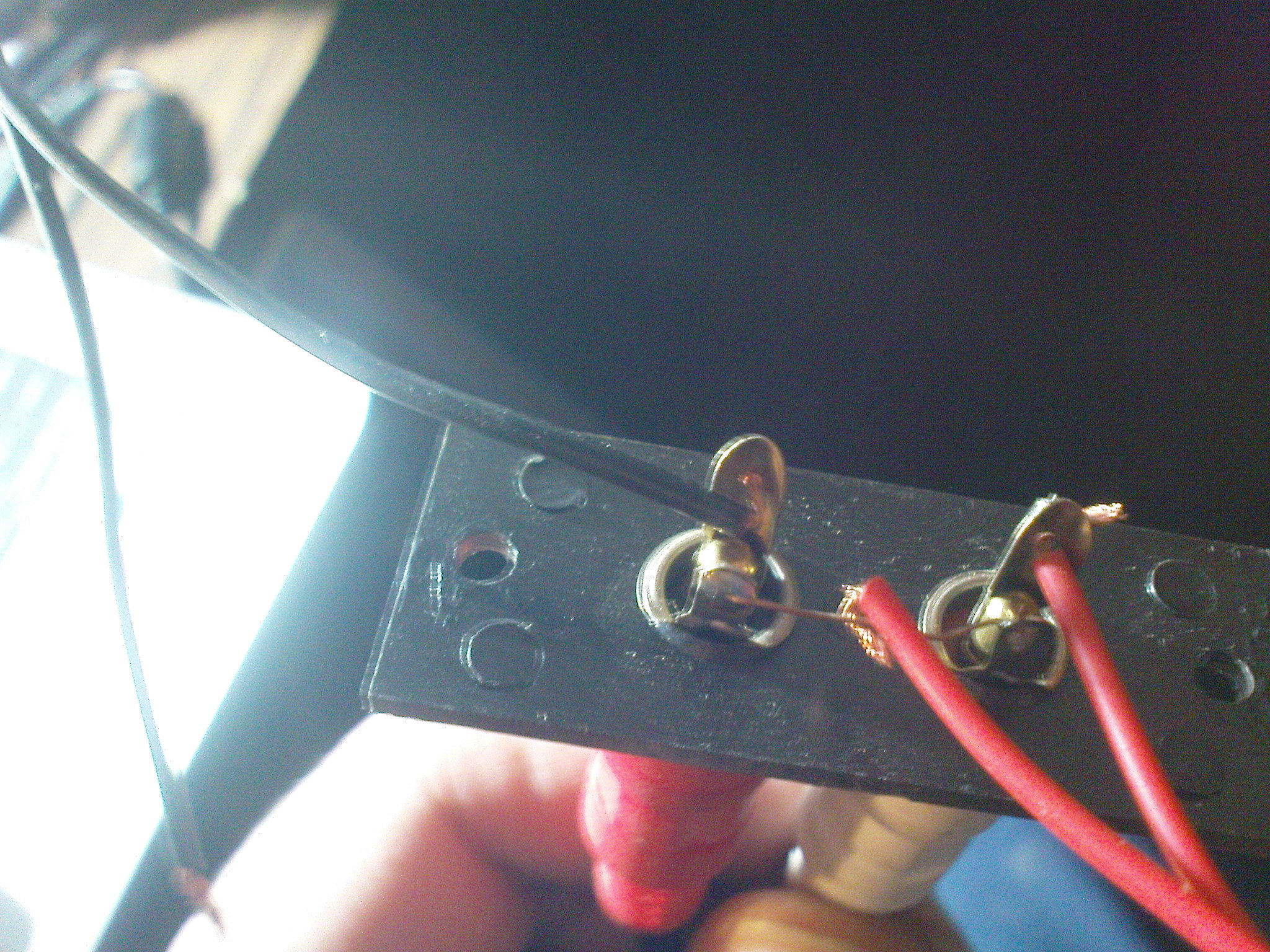
the speaker I use for test:
and if you need more picture I can post anytime but please help me to make these work I try so hard to take a result without any luck
first for PCB:
and here the over picture of components:
the speaker I use for test:
and if you need more picture I can post anytime but please help me to make these work I try so hard to take a result without any luck
Attachments

I tried your PCB with transformer mention before in post 1-5, but no voice out even when I tried both line in the out speaker silence.
Note: I use toner for print the PCB so it flipped the direction let to right and right to left, but the parts and cap all the same as your PCB.
do I need to connect the heatsink to anything? or it just fine and I miss something else anyway I'll post some picture for them soon.
You can not use PCB with flipped direction, or you can put parts on the cooper side of pcb, and wire jumpers (dash lines) from bridge rectifier to right channel must be connect (see post #5)
Regards
thank you very much for this important notes I'll try to fix PCB now again I'll print new one and then I'll post it after it finish again with working pictures as I hope for the preamp.
but I still have little question bridge in post 5 that you make with dash lines suppose to be then under the PCB so then there is two wire from the capacitors to the bridge "if I'm correct" then what does these wires suppose to do I ask just to know because again this is my first amp circuit.
but I still have little question bridge in post 5 that you make with dash lines suppose to be then under the PCB so then there is two wire from the capacitors to the bridge "if I'm correct" then what does these wires suppose to do I ask just to know because again this is my first amp circuit.
thank you very much for this important notes I'll try to fix PCB now again I'll print new one and then I'll post it after it finish again with working pictures as I hope for the preamp.
but I still have little question bridge in post 5 that you make with dash lines suppose to be then under the PCB so then there is two wire from the capacitors to the bridge "if I'm correct" then what does these wires suppose to do I ask just to know because again this is my first amp circuit.
Wire jumper for right channel rail are on the cooper side of pcb, 22k (dash) and smal jumper is only for bridge mode, not connect for stereo.
well I don't know how to thank you for this great one I really imprresed with the sound clear and bass is good also, and as I pormise you before I'll post here the picture for it I hope they clear enough, and I also have notes later hope to help me again with them.
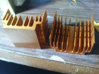
My new PCB fix the old one with right direction now flip the toner to get it correctly:
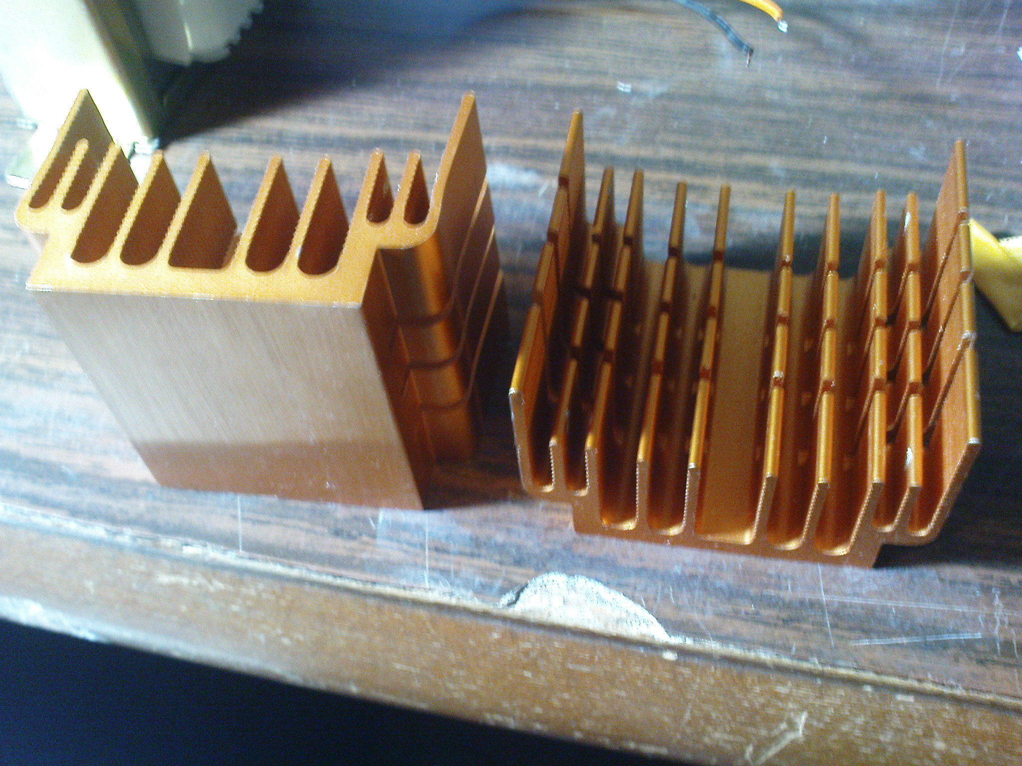
for the cooler I choose those as I was using them for my old PC but I erase the fan and the catcher under them:
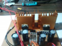
after that I fix the components for the new PCB from the old wrong one:
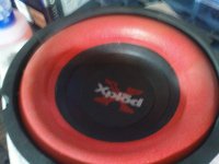
I choose two subwoofer 4ohm 200 xpload sony 8 inch:

connection to input:
for the notes:
1- I have problem with transformer its so hot that I couldn't catch so I use 220v fan 15w to make sure it get cool enough and not blow.
2- for the PCB it work only with one TDA left one without the bridge connection Apex told me about, but when I connect the two bridge both work on mono mod.
3- there is humm without sound but not so high but I can hear it clearly without any other sound is this normal or I should do something to fix it?
My new PCB fix the old one with right direction now flip the toner to get it correctly:
for the cooler I choose those as I was using them for my old PC but I erase the fan and the catcher under them:
after that I fix the components for the new PCB from the old wrong one:
I choose two subwoofer 4ohm 200 xpload sony 8 inch:
connection to input:
for the notes:
1- I have problem with transformer its so hot that I couldn't catch so I use 220v fan 15w to make sure it get cool enough and not blow.
2- for the PCB it work only with one TDA left one without the bridge connection Apex told me about, but when I connect the two bridge both work on mono mod.
3- there is humm without sound but not so high but I can hear it clearly without any other sound is this normal or I should do something to fix it?
Attachments


thank you Mile for your answers its really helpful for me as starter, anyway now I test everything as I hope and wish if you don't mind to give some notes about the results I think people need to know it if they want to build this one
well all come from my general understanding so I hope I'm not wrong with these points:
- when test 2x 8ohm speakers the result was good in sound when the input has high middle waves "1khz, 500hz, 300hz" those I have at my sound card so I'm sure they available to test with any input has EQ.
- when test 4x 4ohm speakers the sound was better and more clear but it less powerful than 2x 8ohm and still good with the mention waves above.
- when I test 4ohm sub 2x the bass was great and loud but I think I miss the filter for output to make signal compatible with sub, in general when I make the input waves with EQ "20hz,60hz, 100hz" the bass was more clear but then I need another amp for speakers and tweeters to hear the full range of sound.
- TDA chips as I notice affected with the output type, so when use sub 8ohm its get little hot, but when I use 4ohm sub it get extremely hot at full load. so I suggest all tester to use big cool heatsink for 4ohm load sub.
- TDA chip that use 6ohm speaker is normal and the sound was the best when test 6ohm 2x speaker on both output channels.
- in general sound get better when I use two transformer for power supply instead of one "well that tested at full load" I use two 22v 500va. they connected as this way:
black wire to the GND for PCB
1st orange wire "1 from first T, and 1 from 2nd T" together to the V- on PCB
2nd orange wire on first transformer free, for the second one to the V+ on PCB
Note: all speakers and sub are the same rate for power, I use 200w for everything mention above.
well last part I want to know what do you think could make best output to make high quality sound ?
is it filters like "EQ, sub filter"
or it could be another thing at the output like materials for example using tweeters , mid , speaker for each output channel.
anyway I want to test now more chips like LM3886 I think after my first one get success then the other one not so hard as I read in the circuit diagram in National about this chip.
You can find amp with LM3886 in my thread: http://www.diyaudio.com/forums/chip-amps/162099-lm3886-schematics-pcb.html
Regards
Regards
thx I'll try also this one for single TDA7294, but I have some question about the whole topic:
do I need more powerful supply to make it work if I want to use them all together?
does the power supply GND need to be connected to all preamp chips together if I want to use power supply for all "single tda, two tda, lm3886 single, cross-x filter"
after all if this true what is the different then between power supply I have seen in pictures that have multiple caps in single to produced 10000uf per rail?
is it better to make the DC volt better or something else?
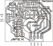
Could you post the PCB and its dimension for this ampThis PCB can be use with TDA7293 or TDA7294, clip work only on TDA7293.
- Status
- This old topic is closed. If you want to reopen this topic, contact a moderator using the "Report Post" button.
- Home
- Amplifiers
- Chip Amps
- TDA7294 Stereo/Bridge with PSU