Just to share some experience
Hi to all!
I recently joined the TDA7293 club and I want to share some of the things I found out, in hope that it will be useful for others to spare some time and money.
I wanted to build an easy amp capable to drive two 400Wrms speakers, so I decided to order two Chinese boards, having 2 paralleled TD7293 v6 CZ each.
Everything worked fine for a couple of hours, I started feeding them with +/- 17Vdc and I raised step by step the voltage up to +/- 47V. Except the strong heat they inflict to radiators specially at voltages above +/-30V, they performed very well till I shorted by mistake the V- wire to GND. All the 4 chips literally exploded with a light and smoke unpleasant show.
I ordered replacement chips from ebay and I got the TDA7293 SINGAPORE.
To replace the blown ones I cut short above the PCB the terminals, and rising the iron temp to 400 oC I cleaned the holes by suction pump, then I soldered back the new chips.
At the very first moment after power on, I had fireworks again, all chips blew up!
This is my graveyard:
http://www.diyaudio.com/forums/<a href=
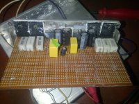
I used a ZIF socket (best was a 16pin ZIF, but I had only a 20pin), 2SC5359 and 2SA1987 transistors, 5.1ohm SYNC and 0.1ohm in emitters.
2x1000uF/50V as in datasheet, and 2x0.1uF very close by TDA7293 supply pins. 22uF bootstrap between pin 6 and 12 (not 14), Input capacitor 1uF polypropylene.
The bottom of the PCB is less handsome
http://www.diyaudio.com/forums/<a href=
And now again about TDA7293. Having the ZIF and no trouble with insulating radiator pads for TDA (since I left the PNP transistor and the amplifier chip uninsulated) I had the opportunity to respond the question about "SINGAPORE" chip. After starting and testing the amp with the "trustful" v6 CZ, I replaced it by one of the ebay "SINGAPORE" chips, being ready for the fireworks show.
Nothing happened this time. The chip is performing at +/-30V EXACTLY as the v6.
Same power, same frequency response, same perception of sound! Only thing not tested by now is the voltage limit of the two flavors differ.
Hi to all!
I recently joined the TDA7293 club and I want to share some of the things I found out, in hope that it will be useful for others to spare some time and money.
I wanted to build an easy amp capable to drive two 400Wrms speakers, so I decided to order two Chinese boards, having 2 paralleled TD7293 v6 CZ each.
Everything worked fine for a couple of hours, I started feeding them with +/- 17Vdc and I raised step by step the voltage up to +/- 47V. Except the strong heat they inflict to radiators specially at voltages above +/-30V, they performed very well till I shorted by mistake the V- wire to GND. All the 4 chips literally exploded with a light and smoke unpleasant show.
I ordered replacement chips from ebay and I got the TDA7293 SINGAPORE.
To replace the blown ones I cut short above the PCB the terminals, and rising the iron temp to 400 oC I cleaned the holes by suction pump, then I soldered back the new chips.
At the very first moment after power on, I had fireworks again, all chips blew up!
This is my graveyard:
http://www.diyaudio.com/forums/<a href=
I used a ZIF socket (best was a 16pin ZIF, but I had only a 20pin), 2SC5359 and 2SA1987 transistors, 5.1ohm SYNC and 0.1ohm in emitters.
2x1000uF/50V as in datasheet, and 2x0.1uF very close by TDA7293 supply pins. 22uF bootstrap between pin 6 and 12 (not 14), Input capacitor 1uF polypropylene.
The bottom of the PCB is less handsome
http://www.diyaudio.com/forums/<a href=
And now again about TDA7293. Having the ZIF and no trouble with insulating radiator pads for TDA (since I left the PNP transistor and the amplifier chip uninsulated) I had the opportunity to respond the question about "SINGAPORE" chip. After starting and testing the amp with the "trustful" v6 CZ, I replaced it by one of the ebay "SINGAPORE" chips, being ready for the fireworks show.
Nothing happened this time. The chip is performing at +/-30V EXACTLY as the v6.
Same power, same frequency response, same perception of sound! Only thing not tested by now is the voltage limit of the two flavors differ.

Hello to everyone, this is my first post and I wish to say many thank's to Dr frost, Mr daniels, Andrew.T ,kebbz.... The list is endless everyone else for great posts as I ve managed to build a bridged amp with single out put transistors 2sc5200 and its complimentary based on tda 7294. Am so happy with the sound as my speakers reached a near breaking point yet still clear loud and very compressed my ears can't complain at all its a HiFi system I gat, schema by Dr frost, bridging by Kebbs. So easy to build, its on a 30-0-30 volts transformer ( 42v+/- rectified) plus 10000mf caps 1 per rail, current on 6 ohms speakers is 5.6 to 6 amps, voltage across speaker load is ~49 to ~50v. On 3ohms speaker current goes up to 10 plus variable. Such an amp would cost a good 700 us dollars in my country yet I made it for less than a 100 dollars. I can't wait to get a 4ohms woofer 400 watts nominal to 1400 watts max. I can't play on 6ohms its too loud am doing a series connection at 12ohms 1/4 volume and I ve to answer my calls outside. Blasting loud.
@ cmorariu I will as soon as I get a bigger pcb as at present am using two separate pcbs they are two separate amps n to bridge all I did was to shot the second input pin3 to ground 0v and connected a wire from pin 2 to pin 14 of the other amp via 22k resistor then connected the speaker to pins 14 of the two amps and boom big sound.
Some pics for my current setup, I bilt these mainly for test purposes so a bit messy but I plan to build a bridged amp with transistors on one PCB as Kebbz but with TDA7294 very soon.
Attachments
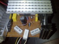
Thank you for the pics! Impressive work. Using such big radiators do you plan to avoid using cooling fan(s) ?
Since you are not ready yet, maybe you consider adding this simple clip detector I made and tested today. It lights a LED for each channel when the output signal reaches the supply voltage limit, telling you when to stop increasing volume to avoid the very common clip distorsion.

You can move the leds on the amp's front panel.

Since you are not ready yet, maybe you consider adding this simple clip detector I made and tested today. It lights a LED for each channel when the output signal reaches the supply voltage limit, telling you when to stop increasing volume to avoid the very common clip distorsion.
You can move the leds on the amp's front panel.
@ cmorarui I will definitely make that clip detector and yes I have the pop power on sound problem it blew up my pioneer tweeters, now i disconnect speakers just to power on, thanx a lot I will replicate it today, a billion words are not enough to thank you. And for the rads I intend to increase the number of output transistors so it can be 1ohms stable, possibly I might make it bridged stereo in 1ohms stable hence the big radiators, after that I can use cooling fans, in future I might make it 4.1 channel.
Regards.
Regards.
If you blew up the twitters, is most probable that your amp has also some ultra sound oscillations (at power on or ringing). It's a good practice to solder a 120pF ceramic capacitor between pin2 and pin3 as close to TDA as possible.
If you bridge two amplifiers, theoretically you get 4x the powe
If you bridge two amplifiers, theoretically you get 4x the powe
Thanx I will definitely add that cap ASAP, last night dismantled both amps and reassembled on a single PCB so now I can use just one heat sink, oh it was quite some work I couldn't get it to work it was just a loud distorted sound so I knew it had to do with the feedback string, I spent the whole day on it, disconnected out puts, un bridged the amps and tried them separately, one worked the other to no avail I wondered till later this evening I took a closer look only to realize I mistook the 2.7ohms for a 680ohms, I guess I was too overworked. Now reassembled and bridged all is fine.
Last edited:
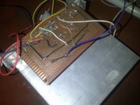
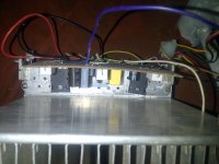
Here is a pick of transformation. I will test its full capability at 3ohms in the morning as previously the other amp with smaller heat sinks would heat up too much so I couldn't, I hope to keep heat dissipation as low as possible even at full capacity.
By the way as it is in this bridged/ sinle output transistor setup is it 1ohm or 2 ohm stable and what will be the advantage of adding another set of out puts? I have another set I would like to add.
By the way as it is in this bridged/ sinle output transistor setup is it 1ohm or 2 ohm stable and what will be the advantage of adding another set of out puts? I have another set I would like to add.
Attachments
The picture you posted I think is not of the finished amp, some components are missing I don't see the bootstrap capacitors that are essential, and one of the 22uF of the two feedback loops. Also the 0.1uF decoupling caps are missing. Anyway the radiator in the picture definitely is too small to dissipate the heat of this bridged amp even if you add a ventilator!
Hi cmurarui, the bootstrap caps are there one is just next to the tda but hidden by the yellow cap and the other is at the bottom of the pcb, I also soldered the 0.1 mf caps right onto the filter caps at the bottom, and yes I omitted the two 22mf caps following the bridged schematic in the data sheets were 680ohms resistors are grounded. As for radiator that's what I could find for now but I will change it ASAP. Thanx.
Calculations on the cross over distortion of the 2 transistor power booster
I did some interesting calculations on the cross over distortion of the 2 transistor power booster after the LM3886, which amp has a worst case slew rate of 8V/µs and typical 19 V/µs.
The slew rate of TDA7293 is even worse: 5V/µs worst and typical 10 V/µs.
The slew rate of TDA7294 is slightly better: 7V/µs worst and typical 10 V/µs
If you want 100W in 4 Ohms you need 20V rms and so about 30V top-top.
According to the Nyquist theorem for a 20 kHz audio bandwidth, you need an amp that accommodates a 40 kHz signal at least in order to reach an acceptable output signal.
Ut = 30.sin(2πft) Volt with f = 40 kHz maximum.
dUt/dt = 30.2πf.cos(2πft) ==> dU/dt (max) = 30.2π.40000 = 7,6 V/µs
This implies that the amp in normal operation is just able to drive a speaker at maximum power.")
In the normal operation, far from the zero point, the output emitter follows the chip 1:1 so the slew rate will be OK. At the cross over point the amp has to jump over from -0,7V to +0,7V via a voltage divider consisting of the “sync resistor” (as Dr Frost Dk calls it, he uses 6,8 Ohm) and the impedance of the speaker load.
If you use a series sync resistor (for ease of computation) of 8 Ohm you can calculate that at the crossing point the slew rate of the amp should be (8+4)/4 * 7,6 = 3 * 7,6 V/ µs = 22,8 V/µs. Even the typical LM3886 is not able to drive this speed.
If you use a 2 Ohm load in order to obtain 200W the slew rate even should be twice as high, which by far cannot be afforded by the amp. Thus (8+2)/2 * 7,6 = 5 * 7,6 V/ µs.
This leads to the conclusion that the sync resistor should have a value very close to zero.
With for example a 0,3 Ohm sync resistor the slew rate requirement is (0,3+4)/4 * 7,6 V/µs = 8,2 V/µs which is tight to the worst value of the amp.
The 0,3 Ohm sync resistor implies that the amp only delivers 2A maximum (Vbe = 2A * 0,3 Ohm = 0,6V of the transistor); at higher currents the transistors will take over.
Conclusion: I advocate a small sync resistor and would be very pleased if some of the guys here could try this in practice and measure the distortion in real live. The ease of construction and stability pleads for this booster; but for better performance it is clear that the solution in which the power supply leads of the amp drives the 2 transistors is far better with respect to distortion.
I did some interesting calculations on the cross over distortion of the 2 transistor power booster after the LM3886, which amp has a worst case slew rate of 8V/µs and typical 19 V/µs.
The slew rate of TDA7293 is even worse: 5V/µs worst and typical 10 V/µs.
The slew rate of TDA7294 is slightly better: 7V/µs worst and typical 10 V/µs
If you want 100W in 4 Ohms you need 20V rms and so about 30V top-top.
According to the Nyquist theorem for a 20 kHz audio bandwidth, you need an amp that accommodates a 40 kHz signal at least in order to reach an acceptable output signal.
Ut = 30.sin(2πft) Volt with f = 40 kHz maximum.
dUt/dt = 30.2πf.cos(2πft) ==> dU/dt (max) = 30.2π.40000 = 7,6 V/µs
This implies that the amp in normal operation is just able to drive a speaker at maximum power.
In the normal operation, far from the zero point, the output emitter follows the chip 1:1 so the slew rate will be OK. At the cross over point the amp has to jump over from -0,7V to +0,7V via a voltage divider consisting of the “sync resistor” (as Dr Frost Dk calls it, he uses 6,8 Ohm) and the impedance of the speaker load.
If you use a series sync resistor (for ease of computation) of 8 Ohm you can calculate that at the crossing point the slew rate of the amp should be (8+4)/4 * 7,6 = 3 * 7,6 V/ µs = 22,8 V/µs. Even the typical LM3886 is not able to drive this speed.
If you use a 2 Ohm load in order to obtain 200W the slew rate even should be twice as high, which by far cannot be afforded by the amp. Thus (8+2)/2 * 7,6 = 5 * 7,6 V/ µs.
This leads to the conclusion that the sync resistor should have a value very close to zero.
With for example a 0,3 Ohm sync resistor the slew rate requirement is (0,3+4)/4 * 7,6 V/µs = 8,2 V/µs which is tight to the worst value of the amp.
The 0,3 Ohm sync resistor implies that the amp only delivers 2A maximum (Vbe = 2A * 0,3 Ohm = 0,6V of the transistor); at higher currents the transistors will take over.
Conclusion: I advocate a small sync resistor and would be very pleased if some of the guys here could try this in practice and measure the distortion in real live. The ease of construction and stability pleads for this booster; but for better performance it is clear that the solution in which the power supply leads of the amp drives the 2 transistors is far better with respect to distortion.
Last edited:
Zanden30, at first glance of this circuit I was temped to make same considerations as yours. I even was tempted to redesign it adding the "necessary" diodes and variable resistor between the bases of final transistors. The clue of this circuit is that TDA7293/4 directly contributes to the output of the amp. No jump is necessary at crossover because TDA itself drives the load at low output voltages. For example for 8ohm speakers, an output of 1.6Vpp is driven only by the chip, you can hear music without any contribution of boosting transistors. They intervene gradually as the output current increases (above 0.1A if the SYNC is 6.8ohm). I tried different values around 6.8 ohm and scoped the output signal. No crossover distortion at all, the only notable difference is that lowering the resistor the "contribution" of TDA increases and it runs warmer. The manufacturer indicates that THD of this chip increases with power, so if you want fidelity you have to keep TDA contribution under 5W.
- Home
- Amplifiers
- Chip Amps
- TDA7294 + Power Transistors AMP (TDA7293 to come also)