Hello, I want to make TDA7293 Bridge/Parallel Amp (as like BPA200 LM3886 Amp).
TDA7293 datasheet show parallel circuit & TDA7294 datasheet show bridge circuit.
I want to know about TDA7294 bridge circuit where capacitor in series with 680 ohm resistor is not connected & why 22k ohm resistor connected between inverting pin of one chip and output pin of another chip.
If i use same bridge circuit of TDA7294 in TDA7293 than what change must be done. If i connect bootstrap pin with bootstrap loader pin than a capacitor is required or not in series with 680 ohm resistor.
I want to use TDA7293 in Parallel because these not reruired precision resistor value for gain setting in parallel mode. (as like BPA200)
BPA200
TDA7293
TDA7294
Please answer. Thanks
I think you can't use parallel configuration mode after you bridge.
You need external circuit to bridge the circuit if you really need to parallel those chips.
For TDA7293, there's master & slave mode for multiple parallel chips
IMHO,
>= 8ohm speaker, better stick with TDA7294 bridge mode (can obtain >150w easily)
<= 4ohm go for parallel mode in TDA7293 (with +-40v , can get >150w )
Last edited:
I think you can't use parallel configuration mode after you bridge.
You need external circuit to bridge the circuit if you really need to parallel those chips.
For TDA7293, there's master & slave mode for multiple parallel chips
IMHO,
>= 8ohm speaker, better stick with TDA7294 bridge mode (can obtain >150w easily)
<= 4ohm go for parallel mode in TDA7293 (with +-40v , can get >150w )
I am no chipamp expert but the BPA-200 is a bridged parallel amplifier and I dont see why either one of them can't be used in that mode.
")
jer
There is a simple way to connect them as BTL mode. However its not practical because of the input impedance..
So the second (and the robust) way is to use a bridge adaptor like this;
- Make two identical TDA7293 amplifier (refer to TDA7293 datasheet page 1),
- Connect the first amplifiers input to the bridge adaptors +OUT,
- Connect the second amplifiers input to the bridge adaptors -OUT..
- Connect the speakers + pole to the first amplifiers out and -pole to the second amplifiers out.
Thats all.
To make a BPA 200 like amplifier with TDA7293s. Then make two identical modular amplifier (TDA7293 datasheet page 10 figure 7) and use bridge adaptor before them as discripted..
...
Not at all..
Last edited by a moderator:
Ok..
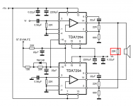
In TDA7294 datasheet. They show the regular way to make a BTL amp. Which is a practical solution. However I think it will be some unwanted results with multi parallel - bridge using with TDA7293..
However if you make two modular 7293 amplifiers and connect them with a bridge adapter then you will have no difficulties like that. Only thing you must concern is the bootstrap capacitor must be 22u x IC quantites, mean if you use two paralell IC per modul then you will use a 47u for bootstrap.
I think it will be a piece of cake for you..
By the way, I have made a modular amplifier with two 7293 chip several days ago. And Its very very comparable with my LM4702 or Pass F5 amplifier..
Last edited:
I am no chipamp expert but the BPA-200 is a bridged parallel amplifier and I dont see why either one of them can't be used in that mode.
jer
BPA200 method require the chipamp configured as parallel rather than bridge. then bridge using DRV134.
IMHO, TDA7293 parallel can produce > 150W using 40V++ PSU & 4ohm speaker which is more than enough to drive big speakers.
Bridged mode a bit risky.
I am currently using a TDA7293 parallel amplifier. I could measure 250W distorted and 200W pure sinus output with +/-42v supply and 4 ohm resistive load. That means you may have a 400W RMS amplifier with just two parallel modules in BTL mode.
Of course under this condition you must consider a really robust cooling.
Of course under this condition you must consider a really robust cooling.
That means you may have a 400W RMS amplifier with just two parallel modules in BTL mode.
Of course under this condition you must consider a really robust cooling.
Too risky, unless lower the voltage to <25v
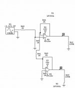
This is the method that I use for a bridged configuration in my sims.
Straight out of the Opamp Aplications Handbook.
After this stage one could easily add more paralled output stages using a dc servo configuration and a unity gain buffer in between the phaze splitter and each of the output stages.
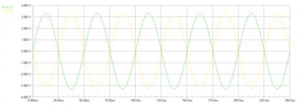
The idea in my design is to keep the propagation delays equal between the two legs of the circiut so that the signal remains in exact 180 degres out of phaze feeding the output stages.
jer
Straight out of the Opamp Aplications Handbook.
After this stage one could easily add more paralled output stages using a dc servo configuration and a unity gain buffer in between the phaze splitter and each of the output stages.
The idea in my design is to keep the propagation delays equal between the two legs of the circiut so that the signal remains in exact 180 degres out of phaze feeding the output stages.
jer
Attachments
Last edited:
Too risky, unless lower the voltage to <25v
I dont think so. Because the modular application is not exactly a parallel amplifier like PA100. For voltage amplification only the first IC's buffer stage is used. The others act as just parallel mosfet output stages..
Currently my modular 7293 amplifers DC offset value is;
0,05 mV..... not Volts just miliVolts
So we dont need a degeneration resistor to connect them together. That means 4 (even more) 7293 can be connected as modular without any problem.
Anyway, in a couple of days I will try the 4 modular with 40v supply. That makes 400W into 2R. I will report the result under this topic.
...
If we add resistor tolrance. How much performance will be effect.
What is minimum right value of resistor tolrance.
In circuits as such of these resistor tolerance is important especialy in the feedback loop just as in the feed back loops of the BPA-200.
I would suggest 1% but if you don't have any then it is adviseble to hand match them.
I was building I voltage divider circuit one day and all I had was some 5% and 10% resistors and I found that many were much more out of spec than what they were rated for.
When you are making a balanced circuit such as a BTL configuration you must take all measures to assure that the gains on both sides are exactly the same.
Not that it won't work but any differences may cause some added distortions in the combined output which may be the reason why some say that their bridged amp doesn't sound as good.
Because in a bridged amp the differences are subtracted to combine the final signal because the two are 180 degrees out of phaze,So any slightest difference in signal level or added propagation delay between the two can add some bit of distortions.
This is also one method of how THD analyzers work as well.
Where as a parallel amp the to signals are added in phaze and the resultant signal is an average of the two ,should one be slightly lower than the other, not causing any added distortions.
Inverting amps have a different gain factor than a noninverting amp with the same values of components ,so I am a not a big fan of mix/match the two in such a circuit.
There are now availible differential output opamps such as the DRV134 as suggested but I have no experience with them yet
I hope that helps you. jer
Last edited:
- Status
- This old topic is closed. If you want to reopen this topic, contact a moderator using the "Report Post" button.
- Home
- Amplifiers
- Chip Amps
- TDA7293 Bridge Parallel Circuit