Can't wait to get my hands on it too, parts list would be great so I can start shopping.
Hi Peterma,
Good to see you're eager to try my pcb. Progress for completion has slowed this week unfortunately, I've had a few other things to do that had priority.
Ryan
Despite my idea of the vertical ground separation around the pin 5 you copy from one of my post elswhere for trying to fix the Distinction v1, I still see at least one error in the pcb !...
look your shematic carrefully...
Hi Eldam,
Yes, in this design i've opted to separate the digital and analog ground planes. Where exactly have you spotted the error? Before I sent the gerbers off for fabrication there was actually a few violations that I fixed up before I sent them.
Ryan
IT was mainly an APRIL FOOL DAY joke !
(btw I just don't care you picked up one of my idea to fix the Distinction V1 after printing to use it here as I writed it on DIYAUDIO... nore you'are making an error here elswhere, but with a 4 layers you didn't need really to make this vertical separation seen on the red gerber than I drawed for the V1 to try to fix it in a two layers corrupted design. Mainly, my 30 euros AYA 2014 pcb DAC is good enough with sota PS...).
This time I will have made a different treatment of the mostly analog -15V and have routed agnd directly to dgnd by a specific trace on a different layer, but not sure this time you can hear it. Because mostly this is more the PS here which will give a "different"result...
Just two cents as it's not my business but your choices. This time the calendar is really yours (as you made for the V1 though )
)
(btw I just don't care you picked up one of my idea to fix the Distinction V1 after printing to use it here as I writed it on DIYAUDIO... nore you'are making an error here elswhere, but with a 4 layers you didn't need really to make this vertical separation seen on the red gerber than I drawed for the V1 to try to fix it in a two layers corrupted design. Mainly, my 30 euros AYA 2014 pcb DAC is good enough with sota PS...).
This time I will have made a different treatment of the mostly analog -15V and have routed agnd directly to dgnd by a specific trace on a different layer, but not sure this time you can hear it. Because mostly this is more the PS here which will give a "different
"result... Just two cents as it's not my business but your choices. This time the calendar is really yours (as you made for the V1 though
)You got me!
But there was a few things I changed before I sent the gerbers. For some reason the via stitching on the digital side went right through the striplines, I must have assigned them to the wrong net. You can see this on the pictures I posted on the previous page.
I'm not surprised you're enjoying the AYA, Pedja Rogic certainly has made a great product available to DIYers.
Update.
Hi All,
Just a small update.
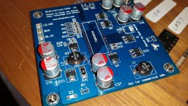
PCBs arrived last week, still waiting for a few parts to arrive. Wurth elektronik, and Coilcraft were kind enough to send me a few samples. PCB quality looks good from PCBway, although I might see if I can find another supplier that can provide 0.1mm between layer 1-2, 3-4 for increased effective capacitance. PCBway provided roughly ~0.17mm.
Starting to get excited now!
Ryan
Hi All,
Just a small update.
PCBs arrived last week, still waiting for a few parts to arrive. Wurth elektronik, and Coilcraft were kind enough to send me a few samples. PCB quality looks good from PCBway, although I might see if I can find another supplier that can provide 0.1mm between layer 1-2, 3-4 for increased effective capacitance. PCBway provided roughly ~0.17mm.
Starting to get excited now!
Ryan
Attachments
Hi All,
Just a small update.
PCBs arrived last week, still waiting for a few parts to arrive. Wurth elektronik, and Coilcraft were kind enough to send me a few samples. PCB quality looks good from PCBway, although I might see if I can find another supplier that can provide 0.1mm between layer 1-2, 3-4 for increased effective capacitance. PCBway provided roughly ~0.17mm.
Starting to get excited now!
Ryan
Cool.
Have you a schematic to share?
LH/S

Bryan,
Begierde ist wahrscheinlich nicht der richtige Ausdruck, ich möchte siehe schematische basiert auf, was sie haben.
Google Translation -
"Desire is probably not the right word , I want to see the schematic is based on what they have ."
LH/S
Hi Ludwig Haus,
So you want to compare my schematics with somebody else's? That's fine but as I said - I have to finish the final design first.
What parts of the schematics are you interested in? Because i've already posted the main power supply schematics. Recently I posted this which has the capacitence multiplier before it. It is basically the same exact schematics I have on the PCB, except for a few different values and minus the capacitance multiplier.
Ryan
Measurements
Hi All,
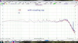
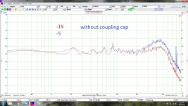
Attached are some noise measurements of -5V and -15V with and without a coupling cap between -5V and -15V.
Now that I have my FFT rig up and running again (VT DSO-2815H), I observed there was a hump at about 50k on the -5V supply. Once I coupled the two supplies together the hump was gone. Ill include this in the final design.
Ryan
Hi All,
Attached are some noise measurements of -5V and -15V with and without a coupling cap between -5V and -15V.
Now that I have my FFT rig up and running again (VT DSO-2815H), I observed there was a hump at about 50k on the -5V supply. Once I coupled the two supplies together the hump was gone. Ill include this in the final design.
Ryan
Attachments
Last edited:
Hi Luke,
Sorry I should have mentioned, yes this is under load from the 1541 while playing music.
Yes you're right, it may not have mattered because it is out of the audio band. But this noise may be a result of current demand from the 1541's internal circuitry. In my mind this voltage is forming because it wants to loop directly back to the -15/-5 supply, so providing a more direct path and a shorter loop is the way to go. In my unprofessional opinion of course.
Cheers
I dont know why you ran two supplies of one rail, but if I did my math right, you got 35nV on the -5 v supply. I think that's pretty good if its real world as I recall Thorsten saying its a noisy ol chip and injects crap on the lines. Any idea what the output impedance of these regs is?
- Status
- This old topic is closed. If you want to reopen this topic, contact a moderator using the "Report Post" button.
- Home
- Source & Line
- Digital Line Level
- TDA1541A Diy Pcb - "Distinction-1541 v2"