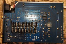
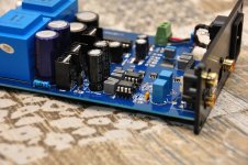
Here's what I've done to the pin7 caps - now two 470uF/10V in parallel, original ceramics removed, chosen for a slim profile so hopefully if I ever get a case for this board they'll fit snugly between PCB and case.
Well, Abraxalito, you inspired me to finally take a soldering iron to this board. I wasn't in a huge hurry, because simply dropping in the better opamps made it quite enjoyable. But, you mentioned before, the pin7 caps bring a little goodness to the bass, and indeed I found the bass a bit lacking in comparison to an off-the-shelf sigma-delta DAC I'm playing with right now. You were right, upping the capacitance across pin7 does appear to kick up the bass noticeably. While I was in there, I removed the 2n2 caps and replaced the 220 decoupling caps with 820s (still haven't added as much capacitance as you suggested there, but this was quick and easy).
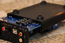
Now I face a more pedestrian problem: despite using those small 470uF/6.3V caps for pin7, they still stick up about 1mm too far for the PCB to slide back into the stock chassis. I'm not sure if the case of those electrolytic caps is conductive either, maybe they shouldn't touch the case? I'm thinking of taking a grinding bit to the bottom of the case where the caps are hitting it, hopefully I can make enough clearance? Then run some strips of electrical tape where the caps will touch. Is there an ideal non-conductive grease or lubricant I can use to help slide that PCB in with the caps rubbing against the case?
Surprisingly this worked first time. Initial impressions - very positive. Its giving less LF colouration than the last set of mods (done on the first instance of this DAC) even without optimization of the power supply (i.e. no outrageous numbers of caps so far).
One other thing I changed on this build is to go for active (single transistor) I/V rather than using the opamps. Its a much simpler solution and not so demanding on the power supply. If there's interest I'll put up some schematics. This sounds like the best DAC I've ever built so far....
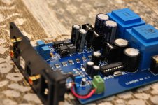
Here are the filters you can see in the photo using the Coilcraft MSS1210 inductors (available from Mouser). Since they're balanced, stereo there are four complete circuits of the filter on the right. The left one is for NOS droop correction of which two are required. In between go the buffers which I'll draw up later. Inputs are on the right btw.
So does that mean you're basically bypassing the stock analog section of this DAC?
I just ordered a couple of the $39 tda1387 x4 DACs Tob Toon mentioned back in post #100. I mainly wanted the PCB, as that's a smaller/simpler layout. I was going to start with the pin7 mod like we're doing here, use my Amanero for USB input, and use a good PSU instead of USB power. Also, I might stack tda1387 chips to up the count to 8x. I was going to experiment with direct out, then see if active I/V was needed... but now you appear to have a nice simple solution, looks like that might mate well with what I have in mind. Thoughts?
Attachments
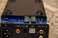
I took my verniers to measure the available height under the PCB - where the stuck-on bump is, the total thickness is 7.8mm. The PCB is 1.6mm so this gives 6.2mm before the caps protrude beyond the bumper. So I wonder if your caps are more proud because of some of the soldered joints absorbing clearance? I trimmed the IC socket legs to allow mine to sit flat to the PCB.
As regards your questions about the analog stage, it seems the bass performance of the DAC is much better when not using passive I/V. I put this down to the pull-up current source in the DAC chip not being designed to cope with such large AC output voltage compliance. After all in the DS there's no spec for AC output voltage compliance, but for DACs that do spec this, its normally small, under 100mV. Using a common base transistor I reckon keeps it comfortably under 100mV - the transistor's simpler and cheaper than an opamp for this function.
I took my verniers to measure the available height under the PCB - where the stuck-on bump is, the total thickness is 7.8mm. The PCB is 1.6mm so this gives 6.2mm before the caps protrude beyond the bumper. So I wonder if your caps are more proud because of some of the soldered joints absorbing clearance? I trimmed the IC socket legs to allow mine to sit flat to the PCB.
Yeah, it was that simple: opamp socket solder joints pushing the caps up just a bit too much. I trimmed 'em down, and could fit the PCB in the case. Unfortunately, that caused something to go askew: in this state, one channel was dramatically muted and the other channel was noticeably noisy.
Those electrolytics were touching random solder joints, the PCB, and the case. I suppose the cans themselves are conductive? Presumably something was shorted. Anything obvious from my description?
I took it out of the case, and now it's running fine. Damn if this thing doesn't sound great! Thanks Malefoda and Abraxalito for the awesome find!
As regards your questions about the analog stage, it seems the bass performance of the DAC is much better when not using passive I/V. I put this down to the pull-up current source in the DAC chip not being designed to cope with such large AC output voltage compliance. After all in the DS there's no spec for AC output voltage compliance, but for DACs that do spec this, its normally small, under 100mV. Using a common base transistor I reckon keeps it comfortably under 100mV - the transistor's simpler and cheaper than an opamp for this function.
If you have a chance, would you be willing to dumb this down a bit for me?
") Most of it went over my head.
Most of it went over my head.Do you have any thoughts on the next best bang-for-buck mods? So far I've (1) added capacitance to pin7 on the DAC chips, (2) put in bigger caps for power decoupling in the analog stage, and (3) removed the 2n2 feedback caps by the opamps.
Thanks again guys!
I'll have another shot at it then.....
The DACs I've built prior to modding this one have been using passive I/V - just a resistor to GND. But to get the best bass they all needed huge gobs of caps on the supply - the latest one I built in Jan had around half a farad (500,000uF). Then when I listened to this Taobao DAC I was wondering how it got such decent bass performance with way less capacitance on the supply (my first modded one has about 100,000uF). I figured it must have something to do with the fact its using opamp I/V.
Active I/V means the output voltage of the DAC varies very little - perhaps just a few mV. Whereas with passive I/V we can see a volt or more on the DAC's Iout pins (6 and 8). Having such a large variation taxes the internal circuitry - I figure the internal current source (providing the 'output bias current' in the DS) is being given too hard a job and its varying its current when the output voltage varies. Or in EE parlance, its output impedance isn't constant with output voltage giving rise to some noise which is correlated with the signal. Fixing (or nearly fixing) the output voltage with an active I/V stage prevents the noise being added and gives the subjective impression of 'tighter, deeper bass'.
This Taobao DAC uses opamps but I figure that a more cost-effective approach is just a single transistor with its emitter connected to the DAC's output, output signal taken from its collector and its base held at a fixed voltage. Otherwise known as a 'common-base stage'.
Any clearer now?
For the next-up mods, I'd suggest current sources on the opamp outputs as with an array of 8 DACs the opamps have to source or sink up to 8mA, well beyond classA operation of the output stage. I use the traditional two transistor current source and it goes between the opamp output pin (pin6) and the -ve supply rail.
Beyond that the next big step is output LC filtering.
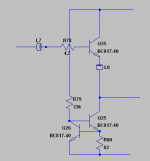
Elcheapo ClassA buffer
Here's the schematic for the classA buffer I'm using (four off) in the latest DAC mods. The two transistors at the bottom form a constant current source - its this CCS which can also be used to bias an opamp into classA. The bias current is set here by the 82R resistor for about 8mA. The transistors are literally 'two a penny' types in SOT23.
Here's the schematic for the classA buffer I'm using (four off) in the latest DAC mods. The two transistors at the bottom form a constant current source - its this CCS which can also be used to bias an opamp into classA. The bias current is set here by the 82R resistor for about 8mA. The transistors are literally 'two a penny' types in SOT23.
Attachments
Any clearer now?
Definitely clearer, thank you! (A big part of the problem is that I lack some fundamental EE knowledge, though I'm slowly picking it up as I go.)
I think you mentioned you also have the kit (PCB and parts only) version of this DAC. I'm slowly piecing mine together, but realized that they didn't label the SMT capacitors. I don't have a capacitor meter. Is there any other way to figure out what capacitor goes where, or should I resign myself to buying a C meter? (I thought maybe I could deduce based counts, but, at least with the resistors, they seemed to include a different number of extras for every value, so I think that's a dicey way to go about it.)
Also, my kit didn't come with heatsinks for what I assume are the voltage regulators. Do you guys happen to know offhand what size they are (I'm assuming it's a standardized kind of heatsink)?
I don't have the kits, I got two populated PCBs (without cases) because the seller was delaying shipment due to unavailability of the metalwork. So I asked him to ship anyway, minus the cases.
The SMT caps are in two sizes (104 and 105) so its probably possible to tell them apart with an ohmmeter - the 105s will charge up slower. I doubt any harm will come if you fit 105 where 104 is specified - you'll be changing the 105s to much bigger 'lytics anyway won't you?
I'll look into what the heatsinks are. They're used for the shunt 'helper' transistors and its probably quite possible to do without them by adjusting the resistor value which feeds the shunt so that the power dissipated in the shunt is kept low. They're 14.6mm wide and 20mm tall, 9.7mm front to back on my board.
The SMT caps are in two sizes (104 and 105) so its probably possible to tell them apart with an ohmmeter - the 105s will charge up slower. I doubt any harm will come if you fit 105 where 104 is specified - you'll be changing the 105s to much bigger 'lytics anyway won't you?
Probably a stupid question, but looks like all the SMT caps are indeed labeled 104 or 105: does that mean that there's literally only two values of SMT caps used on the whole board? And those 104/105 labels are actually tags that indicate the capacitace? I.e. 104=100nF and 105=1uF?
If that's the case, that does indeed make assembly much easier! And I can remove the capacitance meter from my Amazon cart.
And yes, certainly for the tda1387 pin7, I'll use big electrolytics.
I'll look into what the heatsinks are. They're used for the shunt 'helper' transistors and its probably quite possible to do without them by adjusting the resistor value which feeds the shunt so that the power dissipated in the shunt is kept low. They're 14.6mm wide and 20mm tall, 9.7mm front to back on my board.
No need to do any looking, I just thought you might be able to recognize them offhand. Thanks for the measurements though, that was quite helpful. Looks like those transistors are a TO-220 package size. And there appears to be nearly infinite heatsink shapes and sizes for that package. Ebay to the rescue: "20Pcs Aluminum Heat Sink 21x15x10mm(With Pin) For Transistors TO-220" for $3 shipped!
At least in stock form, I think those heatsinks are needed. I've had my DAC turned on, uncased, for only about an hour, and those heatsinks are pretty warm; if I hold my finger on them it gets uncomfortable after about five seconds (my highly precise temperature measuring system).
Yeah I agree in stock form the shunts are rather heavily biassed - the feed resistors are 150ohms for the analog supplies, but I've increased those to 400ohms on mine. I think the input (on the res caps) measured about 22V so this means for the analog rails about 47mA flows but the opamps need only half that (AD845s are particularly thirsty at 10mA a piece). That's one good reason to reduce the rail voltage as 15V rails most certainly aren't needed to output 2VRMS. My rails are at 7.75V.
Running the shunts cooler means more power supply ripple rejection due to the higher series resistance feeding the shunts but also a lower level of ripple to reject because the current draw is lower.
Running the shunts cooler means more power supply ripple rejection due to the higher series resistance feeding the shunts but also a lower level of ripple to reject because the current draw is lower.
Probably a stupid question, but looks like all the SMT caps are indeed labeled 104 or 105: does that mean that there's literally only two values of SMT caps used on the whole board? And those 104/105 labels are actually tags that indicate the capacitace? I.e. 104=100nF and 105=1uF?
Just a hint for any inexperienced folks (like myself) trying to put together the kit version: I realized today that the only 105 caps on the whole board are for pin7. It's recommended to skip the tiny SMTs and go for bigger electrolytics anyway. The 104s are used for pin5, but also several other places on the board. So the kit comes with significantly more 104s than 105s.
And there's actually one other SMT cap value on the board: the 22P near the micro-controller. With my kit, I got exactly two of these caps (there have been one or more spares with all other SMT components) and they were actually labeled.
hi, abraxalito refered me to this thread as I was looking for a DAC to combine with the starving student hybrid millett which I am about to build.
Can I use the TDA1387 4x (as mentioned at page 10 of this thread), mod it with "as much capacitance across the supplies (pins4 & 5) as will fit in the case and 1000uF on each pin7 to pin4 (GND)" as suggested by abraxalito and then use its output directly as input for the SSMH?
Will this work?
(Schematics of SSMH)
An externally hosted image should be here but it was not working when we last tested it.

Ah that's better - however I'm a total novice when it comes to understanding valves. What's the input voltage level this design's expecting?
Thanks for helping me out
I assume you mean the input voltage level of the audio signal; which I tried to look up but unfortunately couldn't find. (power input voltage is 48VDC but I think you knew already). Many people use their ipod or PC onboard audio output as input though...
I have bought both, 4x tda1387 and 4x tda1543.
(Same ebay seller, link in previous post)
Both are very cheap, and sound great.
Very pure, no false detail, a joy to listen to, also for longer periods.
But I have to admit, USB power is coming from a good linear PSU.
Any simple mods to these dac's ?
(output capacitor’s or clock)
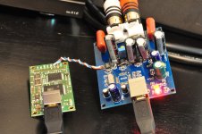
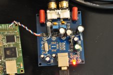
I bought a couple of the tda1387 x4 DACs. When I saw these, I really got my hopes up, that there was a simple parallel tda1387 board that could be easily modded to do what I want. And it is that, to some extent... but the board is kinda chintzy, or maybe I was just too cumbersome with the soldering technique. Either way, I pulled up a couple solder pads while trying to put some 10v/10k uF caps across pin7. You can probably see in the pics where I botched the solder pads, and had to make up for it by soldering extra lead directly to the IC pin4.
But, on the positive side, despite my miserable soldering job, the thing actually works. I removed the CM108 USB IC, and replaced it with an Amanero. The DC blocking caps were no-name electrolytics, so those got replaced with Pansonic 450v/1uF polypropylene caps I had on hand.
Power is still coming from USB. What would you guys recommend as a good DC power supply? I have my eye on this LT3042-based PSU from DIYINHK, though it seems a bit pricey.
It's hard for me to do quick A/B testing, but, listening to it now, I'd say this modded x4 is not too far from its fancier x8 big brother. I'm assuming there's some goodness still to be extracted with a real power supply, instead of my PC's USB power. Although I've only done the three or four easiest mods on the x8... waiting to see what Abraxalito has up his sleeve for that one.
Attachments
Thanks for helping me out
You're welcome
I assume you mean the input voltage level of the audio signal; which I tried to look up but unfortunately couldn't find. (power input voltage is 48VDC but I think you knew already). Many people use their ipod or PC onboard audio output as input though...
The output voltage directly from the TDA1387 chip is limited to 3.5V peak (for a 5V supply). But that's over 1VRMS so will be in the same ballpark as an iPod output. So I'd say yes you can certainly drive this valve amp from a 4*TDA1387 DAC. The I/V resistor should be 820R to 0V and you'll need to ensure you have a coupling cap between the positive side of that resistor and your output.
Although I've only done the three or four easiest mods on the x8... waiting to see what Abraxalito has up his sleeve for that one.
Do you mean you'd like more mod suggestions for the X8 or for the X4?
I haven't got a X4 so far to play with but just this week I got another incarnation of the X8 - the one with the external 15V supply which includes a headphone amp with volume control. When I've played a bit with it I'll post something up - first up I'm looking at improving the internal headphone amp by going to a classA.....
Do you mean you'd like more mod suggestions for the X8 or for the X4?
For a while there, it seemed like you had a new mod for the x8 every few days. So I (mostly jokingly) assumed you had some more to reveal any day now.
However, do you have any suggestions for a power supply for the x4?
- Home
- Source & Line
- Digital Line Level
- TDA1387 x8 DAC: let's check its design, mod it -or not-, play music -or not! :(-