Are you saying that in addition to I/V conversion, the op-amps are also adding some gain?
Its a little bit tricky to talk about gain when the function isn't volts in vs volts out. An I/V stage has what's called 'transresistance' - volts out are divided by current in. The transresistance is the value of the feedback resistor.
Best to describe this as the opamp gets us around the limitation of the output compliance of the tda1387. In passive I/V mode the largest resistor value is determined by how wide a voltage swing the DAC allows (3.5V on a 5V supply), but in active I/V there's close to zero voltage swing because the opamp maintains a virtual earth at its -ve input. So instead of the DAC output compliance limiting the swing, its now the opamp's output voltage swing which is the limiting factor. Which means with an opamp running on say an 80V supply we could theoretically have almost 80V peak-peak if we wanted. In case of a normal audio DAC we just want 5.6V p-p (2VRMS), which is well within the output range of a normal opamp.
Can you help me understand the difference between the one op-amp vs two-op-amp (per channel) approach?
I'm guessing that the approach they've adopted there is an I/V stage using the first OP42 then a 2nd or 3rd order Sallen-Key style filter with unity gain to do some output filtering. That would account for the two opamps and the assortment of caps near the second one.
I realise I'm a bit late on this one, but my TDA1387 kit finally arrived from China via taoboa.
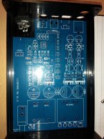
I notice the PCB revision is now 1.3. I can't see any obvious differences from the v1.1 board at the start of this thread, but I've attached a picture for anyone interested.
Planning to do the following initially:
1. Leave out 2n2 capacitors
2. Install additional pin 7 capacitors on the bottom of the board
3. Swap opamps for ad845
Anything else I should consider now that the board is completely empty?
Thanks,
geoff.
Attachments
I'd give serious consideration to only populating one or two of the DAC chips - I can't see that there's really any advantage in paralleling 8 1387s on the same power supply and it only makes the I/V opamp work that much harder to swing the full 8mA, rather than 1 or 2mA. If you go this route the I/V resistor needs increasing to maintain the same output voltage swing (2V) - for 1 DAC chip it should be 5k6, for 2 2k7.
There's now also another very worthwhile tweak available - installing an LC filter between the DACs and the opamp. For more details see here : AliExpress AD1865 R2R DAC
Oh almost forgot - welcome to the thread")
There's now also another very worthwhile tweak available - installing an LC filter between the DACs and the opamp. For more details see here : AliExpress AD1865 R2R DAC
Oh almost forgot - welcome to the thread
Last edited:
I'd give serious consideration to only populating one or two of the DAC chips - I can't see that there's really any advantage in paralleling 8 1387s on the same power supply and it only makes the I/V opamp work that much harder to swing the full 8mA, rather than 1 or 2mA. If you go this route the I/V resistor needs increasing to maintain the same output voltage swing (2V) - for 1 DAC chip it should be 5k6, for 2 2k7.
Thanks abraxalito, I never would've considered installing less dac chips, but makes sense how you explain it. Does it matter which ones get populated?
Am I right in thinking the I/V resistor is the 75 ohm ones next to the opamps?
Thanks,
geoff.
From memory I think the I/V resistor is the one marked 620 (620ohms). At least that's the right value roughly. If you have an ohm-meter or continuity tester you could check that its wired between opamp pins 2 and 6 (oh and its also across the 2n2 which you're not going to fit).
No, I can't think of a reason there's any sensitivity to which DAC sites get chips.
No, I can't think of a reason there's any sensitivity to which DAC sites get chips.
Ah, great to see there is still some interest in this DAC board and response in this thread. I have been lurking on some of the dac threads, hoping to find an understandable diy project to get my feet wet in this daunting (for newbies like me) world of dacs. This thread (together with Matt Garman’s Wiki thread) seems to be within my current limited understanding and capability.I realise I'm a bit late on this one, but my TDA1387 kit finally arrived from China via taoboa.
Great thing is it looks like these boards are still available here: L1387DAC 8X Eight parallel TDA1387 HiFi decoder is the masterpiece of TDA1541!
I’m not sure if I have the guts (or soldering skills) to take on the kit like nlgbo1, but plan to get the populated board only option.
Just a noob question here. I have seen in several posts that dac performance is largely dependent on a low noise PSU. Looking at the first 8 mods listed (in wiki) for this board, none seem to relate to the PSU of this board. Is it not an issue for this dac board? I assume there is an onboard psu and the two transistors are part (or the whole) of that. If I get the populated board, which comes without the transistors – is there an opportunity to improve the psu, and is this a worthwhile consideration?
This particular board is relatively advanced (as Taobao DAC boards go) on its power supplies - its using transistor-assisted shunt regulators, with the transistors sitting on the heatsinks - which have very low output impedance. They can be improved in terms of ripple rejection though (that's their weak point) by substituting a current source for the series resistors - on the very detailed photo @nigbo1 has kindly provided they're marked 150, next to the big reservoir caps.
Which transistors are you talking about in your 3rd paragraph?
Which transistors are you talking about in your 3rd paragraph?
Which transistors are you talking about in your 3rd paragraph?
Sorry - I meant the 15V and 7V transformers!
Ah then that changes things When I was modding my own version of this DAC I eventually ended up moving the transformers out of the case and into their own little enclosure. I did that because there was always some low level hum that I couldn't shift, presumably from flux leakage from these trafos. I had a cat5 network cable running between the trafo box and the DAC carrying the low voltage AC.
When I was modding my own version of this DAC I eventually ended up moving the transformers out of the case and into their own little enclosure. I did that because there was always some low level hum that I couldn't shift, presumably from flux leakage from these trafos. I had a cat5 network cable running between the trafo box and the DAC carrying the low voltage AC.Ah, great to see there is still some interest in this DAC board and response in this thread. I have been lurking on some of the dac threads, hoping to find an understandable diy project to get my feet wet in this daunting (for newbies like me) world of dacs. This thread (together with Matt Garman’s Wiki thread) seems to be within my current limited understanding and capability.
Great thing is it looks like these boards are still available here: L1387DAC 8X Eight parallel TDA1387 HiFi decoder is the masterpiece of TDA1541!
I’m not sure if I have the guts (or soldering skills) to take on the kit like nlgbo1, but plan to get the populated board only option.
Just a noob question here. I have seen in several posts that dac performance is largely dependent on a low noise PSU. Looking at the first 8 mods listed (in wiki) for this board, none seem to relate to the PSU of this board. Is it not an issue for this dac board? I assume there is an onboard psu and the two transistors are part (or the whole) of that. If I get the populated board, which comes without the transistors – is there an opportunity to improve the psu, and is this a worthwhile consideration?
That find looks interesting, and the price is great considering you get a case and the transformers. I might have to get it to try it out. It looks easier to modify than the little giant board.
wow, that same is on ebay for $120 + shipping, quite a difference... makes me think it has to have a trickAh, great to see there is still some interest in this DAC board and response in this thread. I have been lurking on some of the dac threads, hoping to find an understandable diy project to get my feet wet in this daunting (for newbies like me) world of dacs. This thread (together with Matt Garman’s Wiki thread) seems to be within my current limited understanding and capability.
Great thing is it looks like these boards are still available here: L1387DAC 8X Eight parallel TDA1387 HiFi decoder is the masterpiece of TDA1541!
I’m not sure if I have the guts (or soldering skills) to take on the kit like nlgbo1, but plan to get the populated board only option.
Just a noob question here. I have seen in several posts that dac performance is largely dependent on a low noise PSU. Looking at the first 8 mods listed (in wiki) for this board, none seem to relate to the PSU of this board. Is it not an issue for this dac board? I assume there is an onboard psu and the two transistors are part (or the whole) of that. If I get the populated board, which comes without the transistors – is there an opportunity to improve the psu, and is this a worthwhile consideration?
wow, that same is on ebay for $120 + shipping, quite a difference... makes me think it has to have a trick
Note that there are two different versions; blue, which is a bare board + components (so no transformers or chassis) and black, which is the assembled version in a case.
Still cheap though, but I must admit I've not had any experience with "yoycart".
Thanks,
geoff.
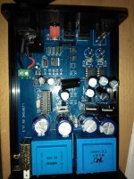
Ok, I've built the board up with 2 x tda1387 and a 2k7 output resistor as suggested by abraxalito.
The DAC appears to be working, I can select the different input, and locks onto spdif signal, but I get no sound output.
I've checked for soldering issues, nothing I can spot, also checked that opamps are getting +/- 15v, that all looks fine.
Quite possible I've misplaced a component or two, as they all just came in a big back with no schematic or labelling.
One question, what are the square output caps on other boards I've seen?
I didn't get those in my kit, so used the 22uf/40v 'Philips' caps. Are these roughly the right value?
Any suggestions much appreciated!
Kind regards,
geoff.
Attachments
Fortuitously I happen to have another DIYer's DAC here for debugging/upgrading so I have fresh experience of what to look for.
You've checked the opamps so do check the DAC chips have the correct voltage (5V) on their supply pin (pin5, wrt GND which is pin4 - or use the shield of the output sockets).
Assuming that's correct the next step is to check the DC levels on the opamp outputs (pin 6) - relative to GND (the shield of the output sockets). Given the DAC chips are outputting current only from a positive supply the opamp's output should be negative wrt GND by about 3V.
You've checked the opamps so do check the DAC chips have the correct voltage (5V) on their supply pin (pin5, wrt GND which is pin4 - or use the shield of the output sockets).
Thanks abraxalito, the 5v line seems to be the issue. I get 5v at the 5v regulator, but not at the test point or dac chips pin 5 / pin 4)
I'm now wondering about the 2 SMD chips labelled 'L' above the 5v regulator?
Anything else I should be looking for?
Thanks,
geoff.
When you say 5V reg do you mean the SOT-223 device next to the mains input terminals? If so that's not where the 5V for the DAC comes from, its a reg for the logic part.
The DAC chip power comes from the TL431 nearest to the microcontroller. Its assisted by the heatsunk transistor (2SA940) right behind it. That shunt config is fed through the 47R resistor buried between two sets of reservoir caps.
The DAC chip power comes from the TL431 nearest to the microcontroller. Its assisted by the heatsunk transistor (2SA940) right behind it. That shunt config is fed through the 47R resistor buried between two sets of reservoir caps.
You've checked the opamps so do check the DAC chips have the correct voltage (5V) on their supply pin (pin5, wrt GND which is pin4 - or use the shield of the output sockets).
Thanks abraxalito, the 5v line seems to be the issue. I get 5v at the 5v regulator, but not at the test point or dac chips pin 5 / pin 4)
I'm now wondering about the 2 SMD chips labelled 'L' above the 5v regulator?
Anything else I should be looking for?
Thanks,
geoff.
- Home
- Source & Line
- Digital Line Level
- TDA1387 x8 DAC: let's check its design, mod it -or not-, play music -or not! :(-