I just bought a mini USB DAC with TDA1305T Chip inside from China (which is on the way to me now) (review: USB DAC using ancient technology)
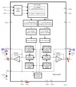
As I've seen on lampizators webpage, the TDA1305T has got identical structure as TDA1549. There's shown a trick on lampizators page how to bypass the internal opamps of the DAC Chip (see attachment file).
I wonder If anyone here has already tried this modification. As I don't have much electronic background knowledge, I've got some questions about it:
- Why does the PIN VDDC 10 has to be cutted ?
- Are the PINS 5 + 6 connected to + or to - signal input of preamp ?
- which output values (mV and mA) does the DAC Chip itself have after modification ?
Thank you in advance for help.
Best Regards
Horst
Attachments
Yes, the reason for bypassing the opamps is that I'd like to get the pure (unamplified) analog output signal from the DAC itself to connect it to an discret analog pre-amplifier (DIY-Version from a friend of mine).
My friend had some very good results with the same mod for a TDA1547 based CD-Player. The Diagramm of TDA1305T says that it should offer the same possiblity.
As I've read some tweakers said that they got a distorted signal after bypassing the internal opamps. So I hope, there's someone who can give me a good advice how to get best result (swictching of the circuits CEXT1 and CEXT2 and then taking I-out signals from PIN 23 and 24 ?)
Have a look what lampizator's result was:
DACMAGIC Cambridge tubed DAC player TDA1305
Contrary to the TDA1547 the R-IV is still in the circuit.
Perhaps you can disconnect the analog supply to the TDA1305?
Hmm ... are you sure ?
look:
http://digilander.libero.it/paeng/a__tda1547_tweak.htm
here's a detailed tweaking description of TDA1547.
The opamps are also inside the DAC Chip.
What would happen if the analog supply of the opamps would be capped ?
Does it still give out a signal when it's capped ?
jockel77, I'm wondering if you made any progress in your quest to bypass the internal opamps of your 1305? I too have a TDA1549 and thinking of bypassing the internal opamps and connect the current output directly to a valve stage. However, I too have very little electronics knowledge so currently searching for the ways to do it.
cheers!
cheers!
Simple answer is that it does not work, of course :
Philips_tda1549
"After intense testing i concluded that the signal is distorted. So I just reversed to the power to leg 10, and signal from legs 4 and 7....."
Removing the power supply to an opamp does not equal to removing the opamp altogether.
Pity. Would have been a nice idea to play around with.
Patrick
I just bought a mini USB DAC with TDA1305T Chip inside from China (which is on the way to me now) (review: USB DAC using ancient technology)
As I've seen on lampizators webpage, the TDA1305T has got identical structure as TDA1549. There's shown a trick on lampizators page how to bypass the internal opamps of the DAC Chip (see attachment file).
I wonder If anyone here has already tried this modification. As I don't have much electronic background knowledge, I've got some questions about it:
- Why does the PIN VDDC 10 has to be cutted ?
- Are the PINS 5 + 6 connected to + or to - signal input of preamp ?
- which output values (mV and mA) does the DAC Chip itself have after modification ?
Thank you in advance for help.
Best Regards
Horst
Interesting question. Unfortunately I cannot disconnect the line between the output switches and the inverted input of the internal OP-AMP so as the 2K2 resistor. Thus the influence of the input load of this internal I/V stage is still the same.
If you cut PIN25 and try to grab the current from PIN24, you have to consider that Rconv2 is still in parallel with the signal line thus some current is still flowing trough it. The amount of that current is unknown because we don't know the impedance of the OP1 when it is powered off. In particular you cannot know if that impedance is linear, this probably introducing distortion. My suggestion is to use OP1 as a good I/V converter (as it is) and to apply the valve 'flavour' in a second stage. Enjoy!
I tried it with a TDA1549 using the attached schematic (came from another thread on this site iirc) which was reported to work.
In my case it didn't work and seemed to destroy the dac chip, quite possibly due to my soldering rather than an error in the schematic.
Regards
Pete
In my case it didn't work and seemed to destroy the dac chip, quite possibly due to my soldering rather than an error in the schematic.
Regards
Pete
Attachments
The circuit you posted sounds like trying to put thing together without solving the originial problem. OP1 and Rconv1 (those internal to the TDA) are still connected to the Iout path, thus they affect the signal you get from pin5.
I give you a hint to solve the issue: the only way you can to grab the signal from pin5 without having it affected by R1 and OP1 is to use a very low impedance path...
I give you a hint to solve the issue: the only way you can to grab the signal from pin5 without having it affected by R1 and OP1 is to use a very low impedance path...
As you can't really remove the op-amp from the analog audio circuit, I did this with a similarly configured DAC chip
Basically I introduce some tube flavor into the op-amp feedback loop.
You may be able to improve the op-amp's output by forcing it into single ended mode, by pulling it up or down.
An externally hosted image should be here but it was not working when we last tested it.
Basically I introduce some tube flavor into the op-amp feedback loop.
You may be able to improve the op-amp's output by forcing it into single ended mode, by pulling it up or down.
TDA1305 current output
I believe I have managed to wire up this DAC, so as to “neutralise” the on board opamp, and thus extract the current output signal.
The method I used, is to float the internal opamp power pin, and then drive the opamp outputs with a low impedance buffered Vref, 2.5 volts, on the Rotel 950 I have modded. This then allows the current to be accessed from the internal inverting opamp input. The compliance seems quite reasonable with perhaps +- 0.5 volt without much distortion. The internal 2k resistor limits the amplitude seen at this point. As a virtual earth point should be connected to this point there should be very little current following in the 2k resistor.
Today I replaced the muting transistors with relays, as they were causing clipping at about -1 volt.
I have only listened with the clipping muting transistors so far and ignoring the clipping the player sounded very nice and clean / clear, even using my pc as a headphone amp.
Attachments
I just started a thread on the TDA1549 based Marantz CD48 which I've today taken the signal off legs 4 and 7 straight to rca's via coupling caps. Works beautifully btw. I'd would however like to do as you are experimenting with to get the purest signal but also noted Fikus point about distortion and decided to leave it out of my plans.
If it can be done I'd certainly try it - I have spare boards if I blow it up...lol
Andrew
If it can be done I'd certainly try it - I have spare boards if I blow it up...lol
Andrew
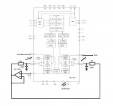
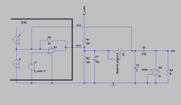
Here is a circuit of the important bits of the mod. The current output is referenced to 2.5v / Vref for best results. These values have not been optimised, but they seem to work well enough for a first stab.
Oops excuse my illiteracy, the opamp is of course an NE5532, only because of its chunky output stage, and I have them lying around!!.
Oops excuse my illiteracy, the opamp is of course an NE5532, only because of its chunky output stage, and I have them lying around!!.
Attachments
I had a dream.....that I could listen to my CD Player without any op amps anwhere !
I've already removed completely the standard dual op amp from my player and it sounds great - transformed in fact - so I guess that disabling the internal dac chip op amps and then adding an external op amp ( if I read your drawings correctly ) takes me back to where I was....
Can it be done without an op amp at all ?
I'm now beginning to think it's the impossible dream !!
The opamp is just being a low impedance power supply to make sure the internal opamps output does not do anything. That is not a complete circuit, you need to decide what to do with the current. The current output can now be treated in a similar way to that of the TDA1543 for example, I would think.
have you studied mr Lampizator?
have you studied mr Lampizator?
Hi
Yes, I've looked at Mr Fikus site for a few years now and have an diy 6N6P buffer inspired by him on the back of my cd player - not literally but it receives CD signal output then moves on to my passive Goldpoint attenuator. For a V out dac it's the perfect way to do it.
If I go ' I ' out I've then got to do it all again and with the stress of another type of valve and the risk of electrocution.....again. Didn't enjoy it much last time and don't wish to do it again.....lol
That said...my valve invention works beautifully, sounds very nice and am very glad I tried and did it.
The whole idea for me was to go ' super clean ' though and no op amps...period...least amount of signal intervention if you know what I mean ?
I'll leave it as it is - I've already got the signal off the dac chip straight to 2 boutique coupling caps and then to rca sockets.
I can't describe the large gains I made just doing this and I now know from the advice of another more knowledgeable ( than me ) and very helpful member that there's potentially a whole lot more to come with the addition of some better components around the dac, independent powering of the dac chip and others plus some attention to the main power supply....oh and some other interesting tweaks too.
Good luck refining this still very fascinating idea though
Andrew
o
One could do a totally passive, if one beefed up the 5 volt PSU a bit and used a circuit a bit like below, trouble is is that it would not be as "loud" as it was.
U1 should be adjusted for maximum output whilst keeping distortion within acceptable limits.
R1 and R2 are made up values to give 10 ohms but higher values may work.
good luck whatever you end up doing,
h
Attachments
Here is a circuit of the important bits of the mod. The current output is referenced to 2.5v / Vref for best results. These values have not been optimised, but they seem to work well enough for a first stab.
Oops excuse my illiteracy, the opamp is of course an NE5532, only because of its chunky output stage, and I have them lying around!!.
Ηι, as the I out is referenced to 2,5V DC Vref, what should be the ground reference for next stage? Let's say that we follow the circuit by applying the I output to the inverting input of an I/V converter external opamp. Where should we reference the non inverting input? To the general ground (DAC ground) or to the Vref (2,5VDC) ? If the second is correct, then what would be the potential output of the external I/V opamp? I hope to make sense
- Status
- This old topic is closed. If you want to reopen this topic, contact a moderator using the "Report Post" button.
- Home
- Source & Line
- Digital Line Level
- TDA1305 / TDA1549 bypass opamps