Due to the way the THAM folding scales making it deeper alone will not work without messing up the expansion, but that might be self explanatory, the only way I know to keep the height intact and increase the depth with maintained expansion throughout the path is to reduce the S1 & S2 and /or the S3 & S4 areas.
If you want to make a lower tuned THAM folded TH here are a few things I kept in mind when designing the original :
Decreasing the S1 & S2 will increase the stress on the driver at higher power levels which might introduce distortion.
Decreasing the S3 & S4 will leave you with less surface coupling to the air outside the box which might negatively impact the overall efficiency.
Increasing the path length alone to tune it lower will most likely reduce the efficiency, if you want to keep the efficiency and tune it lower you need to scale the cross section surfaces along with the path lengths meaning scaled up box dimensions overall.
I do not mean to discourage you from trying this, I only wanted to make sure you know what I see as the potential downsides that might arise in this so you can balance it in a better way from the start if you want to pursuit a lower tuning.
Thanks! I agree the height (and areas) would get larger too or it would lose some efficiency. For example, I calculate your tham15 at 6.6 ft^3 overall, while I could go for a design that's in the 8+ cubes range with a simmed f3 of 35hz in a single. I'll have to take a much closer look at it at some point.
Last edited:
Just pondering... ")
Hi Y'all,
Post #36: "...there are 3 horizontal path sections..."
The THAM15 has four horizontal sections, when you add what I call the Forsman extension to it you get five horizontal sections. How much you gain in which horn section depends on if you move the driver forward towards S5 in the mouth or leave it back against the vertical duct. The reason I like it back is that I found a small improvement in the first dip below (in frequency) the two big tapped horn peaks.
If you have freedom for the external size you can just scale an existing fold, then the areas and the length increase at the same ratio; if you don't want an increase in e.g.: S2 you have to change the flare rate, i.e.: rotate the internal duct inside the external box. If you have to fit a fold into a given box size you most often will have to change the flare rate (angle) to make things fit. It can become a rather time consuming trial and error exercise. Martina's dimensions were almost a natural fit for the THAM15 w/ extension, so it didn't take too many tries to arrive at something that looks pretty good on paper. Bye the way, this can be build w/ only one additional board over the THAM15 if you use a mouth without the additional 45° flares. I think the flares-and some corner reflectors-may help, but I don't know this for sure, and they are not a basic design requirement.
The more I look at the "cone correction" it does look like the way to go as it can be viewed as placing the center of the driver right @ the end of the horn w/ the S1-S2 section becoming a tuning stub of sorts (?). It also makes it very easy to get a sturdy construction in the throat section; you can completely bridge the duct at the center of the driver, and still bring in the duct sides until you just have two S2 size slot openings left and right of the blocked horn path; one opening towards S3, and the other towards S1. You have to watch for excursion clearance...
Regards,
Interesting arguments from all of you. TB46 I lost you in your last sentence about the tuning stub, I try to visualize it in my head but I draw a blank there.
Seems like making a deeper version is out of the question.
Below is one of my tham15 prototypes:


I extended the sides to make room for some handle cutouts. It also makes it stronger in the cone area.
Seems like making a deeper version is out of the question.
Below is one of my tham15 prototypes:
I extended the sides to make room for some handle cutouts. It also makes it stronger in the cone area.
Cone correction
Hi USRFobiwan,
Post #43: "...about the tuning stub..."
I'll attach a picture, hopefully that'll make it clearer? In Hornresp you would just use the usual TH simulation w/ L12 being part of the horn path, in AkAbak you can start the horn flare @ S2, and independently model L12 as a duct attached to S2. More often than not it does not make a difference, but may explain some of the differences between measurements and simulation. I don't have any way to build and measure this.
Nice work on that THAM15!
Regards,
Attachments
This is a work in progress, this far the folding I found that makes the best use of the cabinet dimensions, specially the depth which is critical since it determines the QWR function tuning, can be seen below, this also allows for the minimum amount of outer single wall surfaces (two) in need of coupled bracing :

This is a work in progress, so don't take the above picture to seriously.
i modelled this a few years back
View attachment 591322
View attachment 591323
Here is my TPQWR build from about a year ago.
I use two Beyma 12P80Nd.
Cheers,
Johannes
Here is a fold I messed with and modeled briefly but never built. From what I recall the length was shorter than required for the low frequency extension wanted and the cab size available at the time so I moved on.

When looking at the differences in characteristics between an expanding tapped fold (TH) and a constant area tapped fold (TP) it seems that the expanding fold is more efficient while the constant area has a slightly wider pass band.
Johannes design proposal uses a constant fold in the pre-tapping segment (L23) to set the pass band upper and lower limits, he then adds second (post-tapping) constant area segment which acts as a quarter wave resonator tuned to a mid pass band frequency, this boosts the entire pass band efficiency without compromising the pass band width.
The only expanding segment in his design proposal is the un avoidable L34 transition between the two constant area segments L23 (pass band function) and L45 (the QWR function), the result is a very easy to build and very efficient design consisting purely of perpendicular interfaces.
TPQWR v. TH
Hi martinsson,
Thanks for clarifying, Post @46: "...differences in characteristics between an expanding tapped fold (TH) and a constant area tapped fold (TP)..."
I didn't get it, that the lack of taper was an essential part of the design. But, it still leaves me with a lot of questions. Have you tried to see if there is a difference in simulation between Hornresp and AkAbak? It looks like it may take AkAbak to properly model the L34 transition area. Or could we just assign a very short length to L34 (as in simulating a MLTL) and use TH1 in Hornresp (L23 would go from one side of the driver to the other side, and the end of the L23 pipe @S3/S4 would cradle the driver similarly as you show in your blog for the DSTHAM)? This is all very interesting work.
Regards,
The TPQWR is a series-tuned 6th order bandpass box that uses quarter-wave resonance instead of Helmholtz resonance. You avoid having to use ports, and large cross sectional area quarter-wave resonators sound much better and have a very high efficiency at high power levels. There is no port-compression or distortion due to turbulence. It has a very large radiating surface and a very narrow beam-angle. Just a few steps to the side of the mouth and the spl drops a considerable amount.
I don´t have any problem mounding the driver through the mouth of the quarter-wave resonator even though I need to stretch my arm a bit to reach the springloaded cable connections on the drivers.
Cheers,
Johannes
I don´t have any problem mounding the driver through the mouth of the quarter-wave resonator even though I need to stretch my arm a bit to reach the springloaded cable connections on the drivers.
Cheers,
Johannes


I did actually measure my own arm to see if the required resonator length would allow me to reach and handle the driver, and it should be well within reach for me, and I'm not by any means a tall person, 1,72 (and that's in metersI assume the driver panel is going on the back of the cabinet. Otherwise driver maintenance is going to be hell, or maybe you have the same mutant power as the flexible member of the fantastic 4.
)Using a screwdriver or power tool there is no problem to fix/unfix the driver, what is critical however is being able to rotate the driver underneath the brace and getting it out, this has also been taken into account.
Seeing as servicing happens far less often then using and handling the enclosure I feel it would be wrong to not allow for some difficulties when swapping the driver if it allows for the enclosure design to be as simple and compact as possible, but swapping the driver should not require instructions and I don't believe it does.
That is good to know that we don't need to hire Mr. Fantastic to change drivers
@circlomanen. Really strange to see two totally different graphs, being so radically changes when combined. I assume you made a prototype of the sim and measured with mic, any data on that?
search out danley b&c subs reverse engineered thread.
Posts # 40/44
Hi Y'all,
NEO Dan provided me a drawing that has a more correct location of the cone/surround in the 15NW100. Thanks. I sketched out a side view for the driver, and the respective areas @ S2 and S4. See attached...
Regards,
Hi Y'all,
NEO Dan provided me a drawing that has a more correct location of the cone/surround in the 15NW100. Thanks. I sketched out a side view for the driver, and the respective areas @ S2 and S4. See attached...
Regards,
Attachments
Hi martina,
Post #55: "I found TH218SC, is ist possible to redesign this TH in my empty enclousre for 15NW100?"
To answer this one would have to go through the complete folding process. Looking @ Empty.pdf you want the horn mouth to be on the 410x670 panel? Either way, there is too much of a volume difference to just scale, so it would take a few runs at it to get this done; but it should be possible.
The big question is the CR (compression factor), can the B&C 15NW100 sustain 4:1, and can it push the air load in the resulting horn?
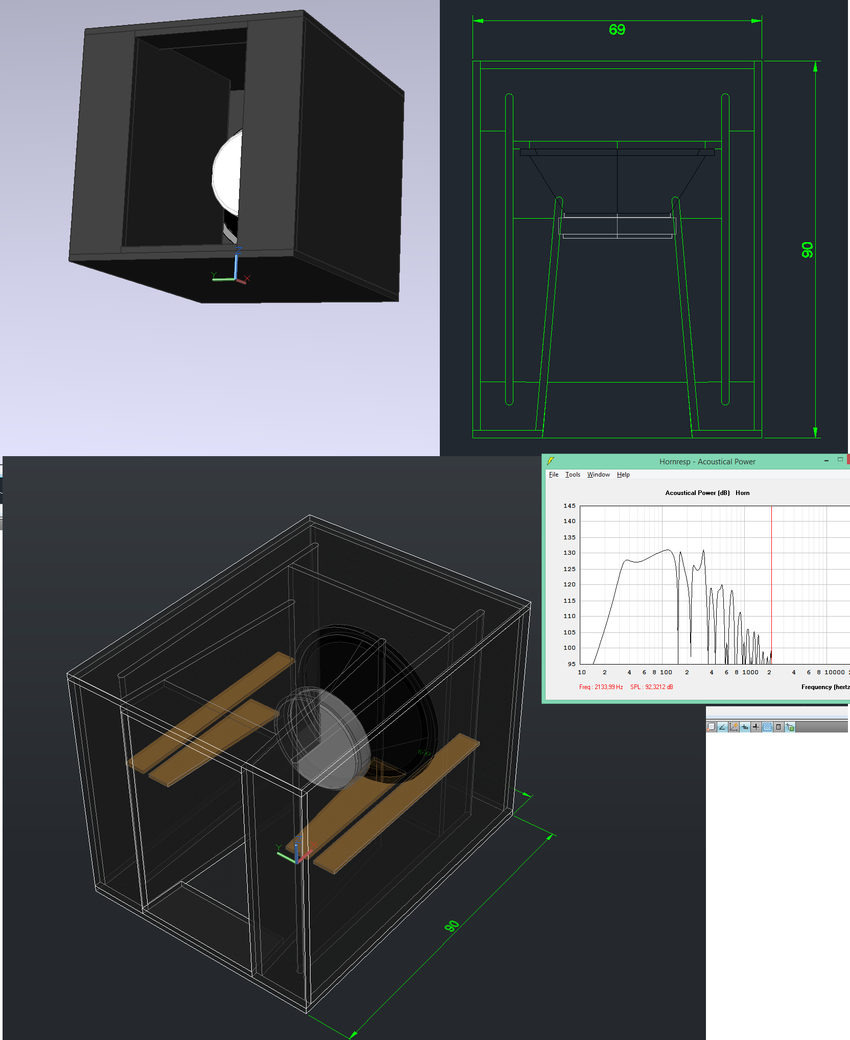
I'll attach a design that uses ~ 4:1, and a combination of fold features from the THAM and SS15 styles; I looks more complex than it is. Take a look @ the angles, they are pretty straight forward, and you can eliminate the bottom flare towards S5 to make it even simpler without giving up anything. It does simulate very nicely. The SPL curve is @ Xmax.
Regards,
Post #55: "I found TH218SC, is ist possible to redesign this TH in my empty enclousre for 15NW100?"
To answer this one would have to go through the complete folding process. Looking @ Empty.pdf you want the horn mouth to be on the 410x670 panel? Either way, there is too much of a volume difference to just scale, so it would take a few runs at it to get this done; but it should be possible.
The big question is the CR (compression factor), can the B&C 15NW100 sustain 4:1, and can it push the air load in the resulting horn?
I'll attach a design that uses ~ 4:1, and a combination of fold features from the THAM and SS15 styles; I looks more complex than it is. Take a look @ the angles, they are pretty straight forward, and you can eliminate the bottom flare towards S5 to make it even simpler without giving up anything. It does simulate very nicely. The SPL curve is @ Xmax.
Regards,
Attachments
-
THAM_SS15_TRY3.txt1,017 bytes · Views: 52
-
Martina_THAM_SS15_Rev01_2017Jan19_TRY3.pdf92.7 KB · Views: 97
-
Martina_from TH218SC_Mod_size_comp_2017Jan17.pdf15 KB · Views: 116
-
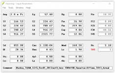 Martina_THAM_SS15_Rev01_2017Jan19_TRY3_Input.PNG17.1 KB · Views: 264
 -
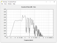 Martina_THAM_SS15_Rev01_2017Jan19_TRY3_SPL.PNG30.5 KB · Views: 278
 -
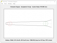 Martina_THAM_SS15_Rev01_2017Jan19_TRY3_Schematic.PNG12.4 KB · Views: 264
Last edited:
Interesting hybrid proposal, as you mention I also feel that perhaps the 4:1 CR is a bit harsh.I'll attach a design that uses ~ 4:1, and a combination of fold features from the THAM and SS15 styles; I looks more complex than it is. Take a look @ the angles, they are pretty straight forward, and you can eliminate the bottom flare towards S5 to make it even simpler without giving up anything. It does simulate very nicely. The SPL curve is @ Xmax.
If one where to decrease the compression simply by increasing the section height at S2 the box dimensions would increase substantially as this change propagates throughout the folding.
Another way to decrease the compression (but less efficient) is if you up the internal width from 410 to 500, making the outer width 537 it might make things better in that regard (just a thought).
Hi Y'all,
Post #55: "...I found TH218SC, is ist possible to redesign this TH in my empty enclousre for 15NW100?"
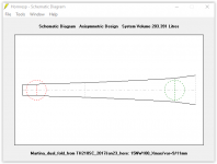
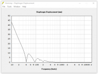
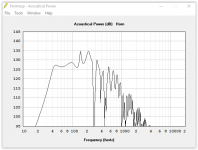
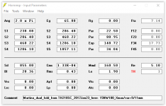
I went through the folding process, and found it necessary to use more than one expansion angle. To keep the angles simple I used S1-S3 @ 3° and S3-S4 @ 6°. The wood does not follow the layout perfectly, but close enough. As expected the low end suffered a little, but the overall output increased quite a bit. CR set @ 3:1.
Regards,
P.S.: change the file named ...._dxf.txt into ....dxf to use the dxf file (AutoCAD 2002)
Post #55: "...I found TH218SC, is ist possible to redesign this TH in my empty enclousre for 15NW100?"
I went through the folding process, and found it necessary to use more than one expansion angle. To keep the angles simple I used S1-S3 @ 3° and S3-S4 @ 6°. The wood does not follow the layout perfectly, but close enough.
As expected the low end suffered a little, but the overall output increased quite a bit. CR set @ 3:1.Regards,
P.S.: change the file named ...._dxf.txt into ....dxf to use the dxf file (AutoCAD 2002)
Attachments
-
Martina_dual_fold_15NW100_2017Jan23.pdf26.5 KB · Views: 121
-
2_fold_mar_1.txt1,013 bytes · Views: 40
-
 Martina_dual_fold_from_TH218SC_2017Jan23_Schemantic.PNG12.1 KB · Views: 52
 -
 Martina_dual_fold_from_TH218SC_2017Jan23_Displacement.PNG25.8 KB · Views: 77
 -
 Martina_dual_fold_from_TH218SC_2017Jan23_SPL.PNG30.2 KB · Views: 214
 -
 Martina_dual_fold_from_TH218SC_2017Jan23_Input.PNG17 KB · Views: 211
 -
Martina_dual_fold_15NW100_dxf.txt149.3 KB · Views: 46
- Status
- This old topic is closed. If you want to reopen this topic, contact a moderator using the "Report Post" button.
- Home
- Loudspeakers
- Subwoofers
- Tapped Horn for B&C 15NW100