I had this book decades ago, can't find it any more:I am afraid my one semester transistor course at school did not cover this subject: what is the relationship between noise, impedance and bias current? All we studied was to bias transistors “one diode drop” or 0.7V.
Low-Noise Electronic Design: C. D. Motchenbacher, F. C. Fitchen: 9780471619505: Amazon.com: Books
All what I remember is one gets lowest noise for BJTs, if h21e is high and Ic is low. Now I follow the general concensus at selecting low noise transistors
") i.e I use what others recommend.
i.e I use what others recommend.Transistor noise
Thank you very much, this is wonderful information. I need to read it over a few times and make some internet inquiries before I fully understand it.
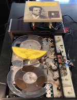
In the meantime I connected the B&K 7003 playback head to a tape reproduce amplifier (Shure M64). Sound was good but very weak. The head measures 13mH and 33ohms. I then inserted a Sony moving coil amp between the head and the Shure. The Sony has 2 and 100ohm selections. With the 100 setting the sound had near “line” level amplitude and was excellent.
I am thinking the head has low inductance as it has to handle very high frequencies for the FM-modulated recordings for its original instrumentation use.
Once I figure out the “tuchel” jack situation, I will run a test tape and figure out frequency response, azimuth, zenith and other matters. In general though this machine is far better constructed than consumer products. Tape path is unusual and treading the tape is truly annoying.
Thank you very much, this is wonderful information. I need to read it over a few times and make some internet inquiries before I fully understand it.
In the meantime I connected the B&K 7003 playback head to a tape reproduce amplifier (Shure M64). Sound was good but very weak. The head measures 13mH and 33ohms. I then inserted a Sony moving coil amp between the head and the Shure. The Sony has 2 and 100ohm selections. With the 100 setting the sound had near “line” level amplitude and was excellent.
I am thinking the head has low inductance as it has to handle very high frequencies for the FM-modulated recordings for its original instrumentation use.
Once I figure out the “tuchel” jack situation, I will run a test tape and figure out frequency response, azimuth, zenith and other matters. In general though this machine is far better constructed than consumer products. Tape path is unusual and treading the tape is truly annoying.
Attachments
Cambridge Phono stage
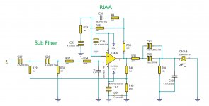
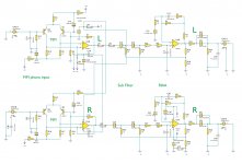
This is the RIAA equalization circuitry in the Cambridge phono preamp I would like to modify.
With my limited knowledge of electronics and getting lost in schematics, it will take me a few weeks of experimentation to figure out what combination of RCs provide the RIAA turnover frequencies, so that I can modify them. (I believe the 7.5ips NAB has two turnover frequencies as compared to RIAA's three, so I will need eliminate one of the RCs.)
If anyone can guide me to a quicker identification of what does what, I would hugely appreciate.
Attachments
Hi tiptop,
1/2 the fun is in getting there. So with that in mind, do a search on Google for a tape head EQ circuit using op amps. Then study the two and see what is different. Teac schematics are fairly easy to find. Why not look up something around the age od a V-800x (I think) that might use an op amp. Then there are the Nakamichi head amps posted that you can compare directly. The only difference is that they threw in a J-Fet before the op amp. Otherwise, it should be directly comparable to what you are asking for.
-Chris
You don't need that subsonic filter on the input too.
R32= 62k
C30= 56n
R31= 2.2k
R33= 39
C33= 470 uF (or short if there is no DC offset).
This is values from Pioneer CT610 deck.
This is EQ for normal tape, for High type (chrom and metal) you'll need switch in EQ.
R32= 62k
C30= 56n
R31= 2.2k
R33= 39
C33= 470 uF (or short if there is no DC offset).
This is values from Pioneer CT610 deck.
This is EQ for normal tape, for High type (chrom and metal) you'll need switch in EQ.
Last edited:
Half the fun
True and that is what I often do.
But for reasons I cannot quite fathom, this part of the hobby is always a bit like reinventing the wheel for me. This is especially true when -- I think -- a designer has first started with a bias resistor, then the RC network and after the design is perfected, he/she has combined parallel or series components into one, to simplify the design, which to me -- an occasional experimenter -- ends up looking like a complete enigma. Whereas people who deal with situations like this on a regular basis see what is what more clearly and early on.
I end up doing a whole bunch of f=1/2(pi)RC calculations around an EQ network till I find a few familiar frequencies, note them down then start playing with component values until I get to measurements that I want. It works but is very time consuming.
This is values from Pioneer CT610 deck.
This is EQ for normal tape, for High type (chrom and metal) you'll need switch in EQ.
Also that is a cassette deck right, running at 1-7/8ips? For 7.5ips reel I will need different values.
Yes that is for cassette decks, for r2r you need NAB values.
Good source for that is datasheets of the some opamps, I will try to find something to help you.
Here are some examples for NAB EQ:
https://pl-1.org/getproductfile.axd?id=1133&filename=LA3160.pdf
http://www.ti.com/lit/ds/symlink/lm833-n.pdf
That EQ NFB network you can put into the Cambridge phono preamp.
Last edited:
Yes that is for cassette decks, for r2r you need NAB values.
Good source for that is datasheets of the some opamps, I will try to find something to help you.
I have used this table which I think is as accurate as they get. For some reason many tape amps do not have the lower frequency correction for 7.5ips. This is a very useful publication to download in general.
Can you tell, in the Cambridge schematic, which combination of RCs are for what constants?
Attachments
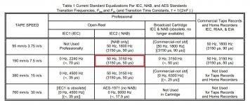
So in brief:
RIAA phono time constants
3180 µs (50 Hz), 318 µs (500 Hz), and 75 µs (2122 Hz)
NAB 7.5ips constants
3180 µs (50 Hz)...........................and 50 µs (3180 Hz)
So to convert a phono amp to tape amp:
-- one turnover frequency needs to be eliminated; and
-- another one moved 25 µs.
In books and magazines, this is explained in extremely -- in my view, unnecessarily -- complicated manner, with references to "constant velocity" and "constant amplitude" alternating one after the other but they are both 6dB/octave downward sloping curves with 2 or 3 corrections, that is all.
Resonance
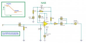
I think I made a mistake, for the sake of clarity, by not providing the fuller schematic. There are stages prior to the RIAA stage which I think would insulate the head from entering into a resonant relationship at this stage, no? See attached.
HF peaking is same as with MM cartridge = C31 sets resonant frequency, R38 sets Q of that resonance.
Both values depends on playback head inductance.
I think I made a mistake, for the sake of clarity, by not providing the fuller schematic. There are stages prior to the RIAA stage which I think would insulate the head from entering into a resonant relationship at this stage, no? See attached.
Attachments
I found your B&K catalog.
This Cambridge phono is way more than tape needs. (Tape does not rumble.)
The app-note for LM833 is an excellent starter tape-amp. The '833 is a work-alike for '5532 which has stood the test of time, and works fine in the same circuit.
You note that the '833 plan uses nearest common value parts, a 5% nominal error, which is hardly audible. It specifically implements 7.5ips Consumer. For 3.75 change 3.6k to 6.48k.
Gain can be raised by decreasing the 200r. If you go below 100r, increase the 47uFd a similar amount to keep bass. If you have to go much below 100r, then indeed these are low-Z heads. Did B&K use a head transformer? Do you have that? If not, *then* the semi-discrete first section of the Cambridge may give somewhat higher S/N. (If you only have mass-duplicated tapes then it hardly matters.)
Attachments
I found your B&K catalog
Thank you very much!
This Cambridge phono is way more than tape needs. (Tape does not rumble.)
True, but starting with a well-preserved, second-hand $100 commercial product results in a much more finished-looking project and more likely than not at a fraction of the cost and time involved too. Just installing RCA jacks on a plasticky Hammonds box can take a whole afternoon and will never look great.
On a separate note, any idea idea what that connector on the B&K is? The PC board clips I installed temporarily are not very secure. Otherwise the sound from the B&K is superb. I will also need to fashion an end-of-tape switch-off mechanism. I guess when they were recording Richter scale-8 earthquakes with it, such creature comforts were not high up on the agenda.
Now I have a very basic question regarding tape recording:
If you record and play back on the same machine, you still need to follow the standard, right? Now taken that the record path has no EQ and is fairly linear (since the head is current driven), why is it necessary to equalize the playback with a corner frequency somewhere in the middle of the audio band? Why not just a simple -6dB/octave EQ, starting let's say at 30 Hz?
Compared to RIAA used at LPs, there is a mirror EQ at the cutting lathe and the turntable. But at tape there is linear at recording and equalized at playback. (Plus the individual HF correction due to playback head inductance and gap width, but this is different for each model).
- Status
- This old topic is closed. If you want to reopen this topic, contact a moderator using the "Report Post" button.
- Home
- Source & Line
- Analogue Source
- Tape reproduce amplifiers