I'm sorry to hear you're not well Graham.
I have been telling and will keep telling people about OB sound and T-bass. One (musician) friend spoke of the OB bass quality in exactly the terms in which I have been thinking about it, and said he'd never have believed an open baffle speaker could make such sound until he'd heard it. He was referring to the articulated, relatively extended and enjoyable bass quality heard in a tiny listening space.
We tried a Dr Dre. CD the other day and it actually had some slam to it, sounding much better than I've heard it on boxed speakers at home. It put a huge grin on my face.
Simon
Hi Graham
Many thanks for your extensive reply. I am also very sorry to hear about your health conditions. Take good care of yourself, that is the most important thing now.
About the speakers: I bought them some years ago and would probably choose other speakers nowadays...but as I have them I will just go with them. I have to say that my listening room is small, and surrounded by neighbours, so I can't go loud anyway. Still I will keep your recommendations in mind.
I never thought about problems from the transition from 18" to 8", but you are probably right. Again, those are the speaker I have and I do not have money to buy others.
I have a shelving low pass filter (that lowers output by 6dB per octave between 20 and 90Hz) and a 12dB Linkwitz Rilley low pass. This is basically what Linkwitz uses in his designs and what seems to be recommended throughout the projects I have seen on the net. But I am willing to experiment with the T-bass as I have most of the components around (with the exception of the inductors). Still I want to study the theory somewhat further, as just putting the circuit as you draw it in place seems like shooting in the dark. For example: your circuit is made for a driver with a Fs of 40Hz, but I would need a circuit good for 30Hz. I will also have to go for passive X-over after the T-bass...that is another big inductor I need to find.
This will probably all take a while as I am busy with some other things. In the meanwhile I will keep reading (and rereading) SimontY thread on dipole design and T-bass. I really like the way SimontY is developing the thread, lots of information and getting better!
Graham, take care!!
Erik
ErikdeBest said:In the meanwhile I will keep reading (and rereading) SimontY thread on dipole design and T-bass. I really like the way SimontY is developing the thread, lots of information and getting better!
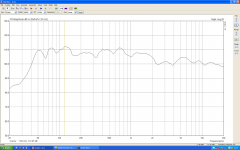
I guess I'd better update that thread then Erik, I did a lot of work last night! I'm glad someone's reading. I need to make the transition between woofers & mid 2nd order now, as I can't remove the excessive mid output from the woofers any other way. Lots to say but this isn't the place as, basically, I think the T-bass part is doing its job wonderfully.
The attached pic might be interesting though - not a bad response for the actual listening position I think. No electronic EQ, all passive. The 50hz is probably boosted by measurement hum pickup.
Simon
Attachments
Hi Eric,
Your 18" might well fall away at MF already, just try without a low-pass between T-bass and driver first to see where your existing drivers need the extra filtering.
It is an L-C low pass network which 'slows' bass, keep an R in series with the C to reduce this effect.
Cheers ...... Graham.
Your 18" might well fall away at MF already, just try without a low-pass between T-bass and driver first to see where your existing drivers need the extra filtering.
It is an L-C low pass network which 'slows' bass, keep an R in series with the C to reduce this effect.
Cheers ...... Graham.
ErikdeBest said:
I have a shelving low pass filter (that lowers output by 6dB per octave between 20 and 90Hz) and a 12dB Linkwitz Rilley low pass. This is basically what Linkwitz uses in his designs and what seems to be recommended throughout the projects I have seen on the net. But I am willing to experiment with the T-bass as I have most of the components around (with the exception of the inductors). Still I want to study the theory somewhat further, as just putting the circuit as you draw it in place seems like shooting in the dark. For example: your circuit is made for a driver with a Fs of 40Hz, but I would need a circuit good for 30Hz. I will also have to go for passive X-over after the T-bass...that is another big inductor I need to find.
This will probably all take a while as I am busy with some other things. In the meanwhile I will keep reading (and rereading) SimontY thread on dipole design and T-bass. I really like the way SimontY is developing the thread, lots of information and getting better!
Graham, take care!!
Erik
Hi Erik,
Your project is very similar to mine, would you mind to share your ideas here:
http://www.diyaudio.com/forums/showthread.php?s=&postid=1660721#post1660721
thanks.
This is very interesting and makes me wonder:
Would 3 DVC 15" per side work with this
(2x4 ohm. qms 5,97. qes 0,38 qts 0,35. fs 20hz. Vas 260L. xmax 14,5mm. Pwr 1000Wrms)
I have 7 Rockford Fosgate RFR 1215 here, and if i run 6 of them as 2 ohm drivers and hook them up in serie i will end up with 6ohm a side.
I do also consider a pair IB manifolds in the roof as an alternative, or eventually install them evenly spaced out in the roof (or will this be a bad idea?)
FE3T said:This is very interesting and makes me wonder:
Would 3 DVC 15" per side work with this
(2x4 ohm. qms 5,97. qes 0,38 qts 0,35. fs 20hz. Vas 260L. xmax 14,5mm. Pwr 1000Wrms)
I have 7 Rockford Fosgate RFR 1215 here, and if i run 6 of them as 2 ohm drivers and hook them up in serie i will end up with 6ohm a side.
I do also consider a pair IB manifolds in the roof as an alternative, or eventually install them evenly spaced out in the roof (or will this be a bad idea?)
As long as you like open baffle bass (fast and light compared to boxed) then it could be very interesting! You'd have a LOT of air-sweeping potential with 6 x 15" woofers

Do it, and please report here!
Simon
Hello Mr. Maynard,
Thanks a lot for sharing this fascinating circuit. However, read through the whole thread, I still do not fully understand the operation. Here I'd like to ask some basic questions:
1. Do the C & L related to the driver's impedance? (single 8 Ohm vs parellel 2 of them) Can we have a formula for all these L, C, R calcuations?
2. You mentioned in the 1st post that <... it is the driver(s) which limit the 'boost' capabilities> How? Can we predict it with driver's parameters and maths?
3. As above, at the first look, the transformer with double voltage output can only provide 6dB of boost, or it can deliver more? What if it's not enough? Now, my own EQ for OB bass uses up about 15dB for extending (relatively) flat to 25Hz. So, can I use a multi-tap autotransformer (or even a variac) for more boost?
As to the load impedance of amp, I guess it'd be not as low. Although the T-bass lowers the effective impedance on the lower frequencies, an inherent peak is there already! So I think the load which amp would actually see is a flatten impedance curve, which should not be a problem for most amps.
If I can get answers to my problems above, I'll surely give it a try. I've been spurring my big dumb woofers for years striving for better bass. This T-bass should be a good shot, I guess.
Thanks a lot,
CLS")
Thanks a lot for sharing this fascinating circuit. However, read through the whole thread, I still do not fully understand the operation. Here I'd like to ask some basic questions:
1. Do the C & L related to the driver's impedance? (single 8 Ohm vs parellel 2 of them) Can we have a formula for all these L, C, R calcuations?
2. You mentioned in the 1st post that <... it is the driver(s) which limit the 'boost' capabilities> How? Can we predict it with driver's parameters and maths?
3. As above, at the first look, the transformer with double voltage output can only provide 6dB of boost, or it can deliver more? What if it's not enough? Now, my own EQ for OB bass uses up about 15dB for extending (relatively) flat to 25Hz. So, can I use a multi-tap autotransformer (or even a variac) for more boost?
As to the load impedance of amp, I guess it'd be not as low. Although the T-bass lowers the effective impedance on the lower frequencies, an inherent peak is there already! So I think the load which amp would actually see is a flatten impedance curve, which should not be a problem for most amps.
If I can get answers to my problems above, I'll surely give it a try. I've been spurring my big dumb woofers for years striving for better bass. This T-bass should be a good shot, I guess.
Thanks a lot,
CLS
Hi CLS.
Argh !!!!!! A conditional 'I'll give it a try'
Conditional on my replies satisfying your understanding based upon existing published data ?
Don't take offence, but where is your sense of adventure ?
Your empirical curiosity ?
Don't tell me these have become limited by established applications of known theory, for whilst the theory itself has become established, that does not mean its application is always to best advantage; especially for (non-sinusoidal) audio !
Maybe my answers to your questions will reveal that T-bass embodies more than is perceptible to the 'theoretical' eye.
Good questions though !
1) No.
The C+L relate to the radiation peak due to the driver plus mounting/enclosure induced characteristics.
The C+L can be as easily tuned to flatten an IB peak as an OB peak, eg. to obtain even better LF from a tiny full-range cabinet.
Components act in parallel/series with the amplifier but only in series with the driver, impedance being lowest where necessary for direct LF voltage drive. Thus L+C component values will be similar for two drivers in parallel as for one on its own, though will need to be trimmed slightly due to the change in resistor/winding resistance values which do need to significantly match effective driver R.
2) Not simple at all. The*perception* of radiation characteristics depends upon so many factors still not covered by existing software.
Not just to the driver either - but how it is used/mounted, for the driver is but one series component within the reproduction chain.
At least the C+L cover a wide range of possible uses.
3) Twice voltage - four times power - yes at LF, and with respect to the driver's developed impedance at LF, which is often at least twice nominal and thus already half power anyway.
However the C+L+Rs still load the amplifier when the driver impedance goes high, and with the C+L acting more in phase (with the driver's dynamic response) at the 'ground' tap, this implements a cut at the frequencies they tune in series with the driver itself, thus establishing a working range similar to the one you EQ at 15dB, though without the same EQ induced phase change !
>> an inherent peak is there already << yes with conventional direct connection plus mounting.
However the T-bass slightly reduces the effect of that peak by boosting below it, also cutting above via increasing waveform developed impedance in series with the driver where an enclosure or corner sited baffle would otherwise induce a peak at some frequency above normal driver Fs.
Yes the amplifier load can be flatter than that due to driver/enclosure/baffle resonance alone, ie. not as high as that due to resonance seen on an impedance chart, and thus providing more realistic sounding LF kick (again adjustable via resistor selection).
Our problem is not the "big dumb woofers", but the dumb way in which we have for so long been driving them without consideration for their electromechanical characteristic changes in behaviour which develop during music time in response to the audio waveform we feed them (resonance and energy storage). The T-bass circuit can be adjusted to counter these changes in a manner which cannot show up via sine or simple simulation !!!
Predictable ? - nah. I could design/simulate circuits/loudspeakers which will provide a predictably flat measurable response, but they will still sound so unconvincing, or worse - tiring, when attempting to reproduce real (non-mathematical) audio waveforms.
We need to experience and develop 'hands-on' what is possible, without being influenced by DEAF software !
Cheers ....... Graham.
Thanks a lot, Mr. Maynard,
And sorry if my conservative attitude upset you. In fact your T-bass circuit grabbed my attention at the very beginning (in Lynn Olson's mega thread IIRC). However, it just takes time. I'm in the miserable middle age and mostly live for other's needs. Leisure time is so little, I have to use it very effectively. See, I'm typing here in the office during working time by company's computer.
Now I got a clearer picture and it'll be closer to the real action. Before that, I have an idea. I redrew (and simplified) the circuit:
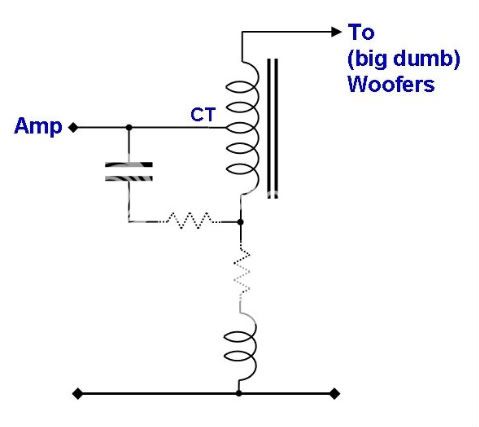
This is mainly for easier understanding (for myself). And one step further, what if using a 'real transformer':
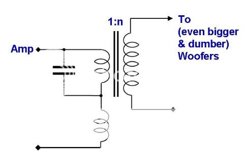
It's because I found some transformers in local shop with windings of [110-200-220V : 380-400-415-440V ] and various current capacities. I think such transformer should be very flexible for this usage.
Any comments?
And sorry if my conservative attitude upset you. In fact your T-bass circuit grabbed my attention at the very beginning (in Lynn Olson's mega thread IIRC). However, it just takes time. I'm in the miserable middle age and mostly live for other's needs. Leisure time is so little, I have to use it very effectively. See, I'm typing here in the office during working time by company's computer.
Now I got a clearer picture and it'll be closer to the real action. Before that, I have an idea. I redrew (and simplified) the circuit:
This is mainly for easier understanding (for myself). And one step further, what if using a 'real transformer':
It's because I found some transformers in local shop with windings of [110-200-220V : 380-400-415-440V ] and various current capacities. I think such transformer should be very flexible for this usage.
Any comments?
Hi CLS.
Your second re-draw won't work unless the lower output connection is joined to the junction of the L and C.
Transformer windings generally need to be 20 to 40V per half at 3 to 6A, also <1 Ohm, preferably circa 0.1 ohm.
Line/mains voltage autotransformers are not going to have low enough resistance to drive LF with low source impedance, and if used are likely to impair LF reproduction.
The best transformers to use are typical high power SS amplifier PSU types; say 40-0-40V and 500VA, though the likes of 1x (or 2x) Alpha-15A (s in parallel) could be driven with say 20-0-20V at 300W.
Cheers ....... Graham.
My impression is that the T-bass ciruit does something very similar to a Linkwitz transform. What makes it interesting (and probably uncalculable) is that it cleverly takes advantage of the interaction between cross-over components and speaker.
Is your experience that they all work very much the same at a given voltage and power rating, no matter what manufacturer and no matter what type (EI or toroid, e. g.)? Because otherwise buying and trying may satisfy one's sense of adventure, but might as well leave you penniless before finding the right transformer.Graham Maynard said:The best transformers to use are typical high power SS amplifier PSU types; say 40-0-40V and 500VA, though the likes of 1x (or 2x) Alpha-15A (s in parallel) could be driven with say 20-0-20V at 300W.
Hi pacificblue,
The Linkwitz transform can optimise for sine response, but not driver dynamics, where first half cycle amplitude loss is not countered. The T-bass can counter a driver's first half cycle (dynamic) loss, and allows a single amplifier to power all low/mid/high drivers.
Higher Q Alpha-15A drivers can be overdriven at LF with circa 25W, whereas some lower Q drivers, especially those of lesser VAS and low efficiency, will still not be overdriven in free air with maybe 200W.
Thus the Alpha-15A is a special case, and most of the others likely to be good on an OB should work well with a 500VA component which is unlikely to saturate before the driver reaches its limits.
Also I cannot begin to express how important it is to minimise winding losses, this being where the 500VA transformer will not be found wanting with low Q drivers.
EI types have higher winding resistances, so best to go for a typical power amplifier PSU toroid.
Cheers ....... Graham.
I have not compared them directly for myself (yet) while read quite a lot about the sound difference between those cores.
Many say iron core is superior than ferrite (in signal relaying applications) because of better magnetic conductivity.
In the end, I guess it's all trade-off between coil's resistance and core's conductivity.
Many say iron core is superior than ferrite (in signal relaying applications) because of better magnetic conductivity.
In the end, I guess it's all trade-off between coil's resistance and core's conductivity.
Hi CLS
In this circuit the transformer is for LF and does not need to work at mid/hi frequencies where core characteristics would be much more important.
However, toroidal transformers do tend to be bifilar wound, which means there is much closer coupling through medium frequencies anyway.
Cheers ........... Graham.
I enquired local winders about the "adequate" 500VA transformer (0-40-80V autotrans). With EI core, it'll be huge -- core type is 133 x 60mm, estimated weight is 8kg! And quoted at about US$100/ea !! Toroid type would be much cheaper at about 1/3 cost. (Those 2 are from different sources, so they may not be identical in quality though....)
Yesterday I made a simple set up for a little experiment. The components on hand were only enough for 1 channel. And all other conditions were very very crude (keeping most of of my original setup and just adding the T-bass):
1. 4.5mH choke with 10000uF cap (to bring the 'shoulder' down to about mid-20, I roughly calculated by the LC resonance) No series R.
2. a small transformer with 0-6.3-12V winding (originally designed for tube pre... oh well.... )
2. original active x-over was kept (1st order 40Hz LP in the line stage, mated with 160Hz HP section with boosted gain), additional upstream digital EQ was kept in the signal path but reset to flat under 200Hz. (previously there was about +/- 3~4dB adjustments)
3. maybe a big no-no -- 6L6 P-P tube amp! (I don't have SS amp on hand, sorry )
4. woofers are Eminence Sigma Pro18, 2 per side, parelleled, on a baffle of 1.2m wide x 1.1m high. I don't have a 2 Ohm tap on the OPT of tube amp, so I wired them across the 8 and 4 Ohm taps.
At first, the volume was down quite a bit (I guess maybe the load was a little bit tough to the tube amp). Luckily I got input gain control on the tube amp. Winding up the knob to bring back the balance, then it began to show the potentials.
Ever since I tried active xover (especially at the bass), I never go back to passive -- those 'obstacles' between amp and woofer make huge damage to the sound.
Surprisingly, all these windings in T-bass did not show the 'blocking' effect I used to experience with passive xover. I switched between channels and found the bass with T-bass was livelier, and more tuneful.
And the dynamics was enlarged! The initial attacks of drums and basses came out with explosive-like blows of air. Those front edges of the bass notes were indeed with more impact energies.
Don't get me wrong, I know the real front edge of 'transient response' is high frequency, not bass. So, when I mentioned 'more impact energy', I did mean the hammering of bass -- thus the overall sound came out with more fullness, weight and authority. These characters are just what I thought lackings of a dipole bass. T-bass makes an OB bring back the impact power and solidity of a monopole bass. Amazing!
My setup was far too crude to be a proper one, however it showed the potentials very well. Now I'm going to find some proper parts.
Yesterday I made a simple set up for a little experiment. The components on hand were only enough for 1 channel. And all other conditions were very very crude (keeping most of of my original setup and just adding the T-bass):
1. 4.5mH choke with 10000uF cap (to bring the 'shoulder' down to about mid-20, I roughly calculated by the LC resonance) No series R.
2. a small transformer with 0-6.3-12V winding (originally designed for tube pre... oh well.... )
2. original active x-over was kept (1st order 40Hz LP in the line stage, mated with 160Hz HP section with boosted gain), additional upstream digital EQ was kept in the signal path but reset to flat under 200Hz. (previously there was about +/- 3~4dB adjustments)
3. maybe a big no-no -- 6L6 P-P tube amp! (I don't have SS amp on hand, sorry
)4. woofers are Eminence Sigma Pro18, 2 per side, parelleled, on a baffle of 1.2m wide x 1.1m high. I don't have a 2 Ohm tap on the OPT of tube amp, so I wired them across the 8 and 4 Ohm taps.
At first, the volume was down quite a bit (I guess maybe the load was a little bit tough to the tube amp). Luckily I got input gain control on the tube amp. Winding up the knob to bring back the balance, then it began to show the potentials.
Ever since I tried active xover (especially at the bass), I never go back to passive -- those 'obstacles' between amp and woofer make huge damage to the sound.
Surprisingly, all these windings in T-bass did not show the 'blocking' effect I used to experience with passive xover. I switched between channels and found the bass with T-bass was livelier, and more tuneful.
And the dynamics was enlarged! The initial attacks of drums and basses came out with explosive-like blows of air. Those front edges of the bass notes were indeed with more impact energies.
Don't get me wrong, I know the real front edge of 'transient response' is high frequency, not bass. So, when I mentioned 'more impact energy', I did mean the hammering of bass -- thus the overall sound came out with more fullness, weight and authority. These characters are just what I thought lackings of a dipole bass. T-bass makes an OB bring back the impact power and solidity of a monopole bass. Amazing!
My setup was far too crude to be a proper one, however it showed the potentials very well. Now I'm going to find some proper parts.
Hi CLS,
As I read through what you are using there I thought "Oh- No - that is such an unfair test".
I expected you to report that you would be going away disatisfied.
I have quite literally been working with transistors for more than 45 years (finished with tubes 30 years ago), and there has never been any way I can implement the actions of this circuit 'actively'.
Loudspeakers are CURRENT driven and modifying the drive voltage is tantamount to expecting two wrongs to make a right.
Now that you have a start you can try different values of choke (higher), capacitor (much lower) and eventually a larger transformer (higher VA). The L and C should match the frequency/shape of the desired response, not be scaled to match the driver impedance !
It is the LF voltage voltage step-up which gives the driver an extra phase coherent kick, and then the resonant L-C which deprives the LS of that additional muddying drive which causes it to boom resonantly. That L-C circuit is simultaneously series tuned wrt the amplifier so it also loads the amplifier output where driver resonance cannot.
Your driver is low Q too - so I bet it sounds reasonably tight even with sub-optimum drive. Many explain 'kick' as coming from the higher frequencies, but here you are noticing the kick because it hits more phase coherently, as with real drums, not with the multiply independent group delays which can arise with active EQ, standard passive arrangements and the driver itself (especially if higher Q).
Transformer bass makes monopoles sound awful by comparison, even though OBs can't radiate as powerfully as a subwoofer !
No way back from here you know !
You might even find you can back off on some of your already existing EQ/crossover type arrangements and let the T-bass do more.
Cheers ........ Graham.
As mentioned, that crude setup is just a preliminary experiment. Will surely look for proper parts and give it a good fine tuning.
Oh, some other questions on LC resonator :
As my shallow understanding,
1. Fc is negative related to LxC.
2. Q is higher when the C gets bigger/L gets smaller
So if I want it lower, I use big L and C.
If I want the boosting peak higher (in the frequency response), I use even bigger C, and keep or reduce the L, ... etc.
Is that right?
Hi CLS.
The C+L cause tuned CUT - not boost. This is tunable to frequencies where the driver/baffle introduce unwanted gain.
The Q of cut response is controlled by series resistance and not the C and L combination.
High C causes flat output above L-C resonance and cuts part of the boost that L is otherwise capable of implementing. Do please try reducing the C, you might well then be able to reduce other phase shifting EQ or LP you are already implementing.
The boost is not tuned, it arises due to the transformer and series L. You do not want the boost above say 80Hz, so you might well need to increase your value of L.
The best way to gain an understanding of this circuit is by trying different component values, and I can't see a value of C greater than 2,200uF being useful.
Cheers .......... Graham.
- Home
- Loudspeakers
- Full Range
- 'T'-bass drive for OB LF drivers.