...
This one here is a patent by Toshiba which comes quite close to our proposals. Although the technical implementation is different to our proposals the general idea is quite close. From the legal perspective the claims would have to be analysed in detail in order to be sure.
...
Espacenet - Bibliographic data
Yes, this seems to be close. The sketch and abstract on the cover look very close to Charles approach. Less close to the method according posting #3, but in fact all claims would have to be checked before commercially using any of our discussed ideas for the dynamic hysteresis.
P.S. I think legal perspective does not just mean the claims, but also who can afford the stronger attourneys for unlimited time.
In any case it should be clear to every reader that the coming amp is not intended for commercial business. Neither from legal perspective nor from design perspective.
It is simply for DIY enthusiast, who know about dangerous voltages.
IR do a 1.7KW amplifier project using IRs2092 and gate buffers to up the gate drive.
Variable frequency response w.r.t. load, pre-filter feedback projects

I wonder if you could use a window comparator, followed by an S-R latch as the modulator instead of a single comparator with hysteresis? I used the same arrangement in the past where I wanted variable hysteresis without all of the tolerance issues that setting an accurate hysteresis level involves. You have to provide symetrical threshold voltages to the window comparator to set the (emulated) hysteresis effect, but that shouldn't be too difficult, although very high speed op-amps would be required to follow the switching waveform. A hastily drawn Visio pic is attached.
Brilliant, the threshold could be set very easily thru symmetric current sources/mirrors.
How do we determine the transfer function for the required hysteresis level in relation to the output signal peak value? I see that the original schematic used the input signal level to determine this, whereas the main effect on the self-oscillation frequency will be how close the output signal approaches to the supply rails. For most of the output signal range, the self-oscillation frequency does not change much, but the frequency starts to drop quickly as the peak of the signal gets closer to the supply rail voltage. I guess that the control signal into the (non-linear) signal processing block that determines the hysteresis level has to be from circuitry that provides a 0V-referenced voltage, proportional to the absolute value of the difference between the output signal level and the relevent +ve or -ve dc supply rail voltage?
Hope this makes sense, I've been thinking about this over lunch!
Hope this makes sense, I've been thinking about this over lunch!
I see that the original schematic used the input signal level to determine this
Sorry, I meant in the schematic that Charles posted in #52.
I'd say it is actually a function of the audio (!) signal at the input of the modulator. If taken from the output filter you'd have a lagging control signal which might also cause distortion at higher frequencies. It would be best to regard the AMP as LTI system and determine the LTF from input to modulator and use this LTF to EQ the input signal accordingly before feeding it the hysteresis modulator. The next step to increase accuracy would be to determine whether a simple proportional factor is OK or if some nonlinear processing would be needed as well.
Regards
Charles
Regards
Charles
Last edited:
My first sims of the clamping method took the signal from the input with an OP amp, but it was much less convenient to parametrize.
The difference between output signal and rail is the key to understand the frequency shift and output voltage ripple
Towards the close rail you need very long ON times to derive a certain change in the output voltage, the fastening towards the other direction cannot compensate this.
Note, towards the close rail the driving voltage across the output chokes converges to zero and consequently the necessary ON time converge towards unlimited, while towards the far away rail the voltage across the choke will not more than double vs. idle situation. Besides the voltage across the choke, also the superimposed low frequency current influences the the relation of ON times and different dv/dt of both directions - but it does not change the overall picture in a fundamental way.
Above observation and considerations together pushed me to improve the hysteresis modulator by designing a circuit which uses the difference between output and rail as control criteria instead of the input voltage.
Hi Charles,
no matter if Ouroboros and myself are pointing more to the difference between output and rail, this still allows a math modelling similar to your proposal.
It would just need to introduce a term with a difference vs a constant which is reflecting the (weighted) rails.
Well, rail sagging would again complicate the equations, but I think everything is possible.
It is just a question from which direction we look at the system.
When coming from distortion, it is absolutely making sense to describe the correction term as a function of the audio signal at the input.
When looking to it from the perspective of output ripple and frequency shift it is more intuitive to use the difference between output and rail.
By the end of the day we do not change physics by our math model.
Also the similarities of the simulation results of both implementations does not show massive short comings in any of both approaches.
I was not satisfied with the performance of my 320kHz design and at the same time I was not happy with the 400kHz version which would chase IRFP4668 at 400kHz/160V/60A hard switched.
In the mean time I have settled a new adjustment which is fitting mostly my taste.
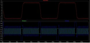
It has a comfortable idle switching frequency around 320kHz, good step response and bandwidth around 80kHz.
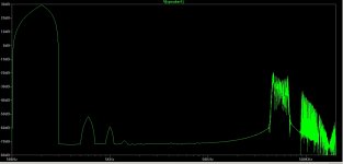
Harmonics at 400W/2R are in the -80db range, means further optimization by simulation would be completely meaningless, because in this range simulation and reality typically differ already pretty much.
Output voltage ripple is slightly below 500mVrms during idle.
No lunch for free.
These selfoscillating topologies are a tight knot in it self. No matter what you change, all other parameters change as well. Swichting frequency, loop gain, carrier shape, output ripple, step response...
Achieving overall good results with 320kHz does consequently lead me to a design with higher output filter inductance. 18uH.
Ok, that's not really high and for ripple current load of the e-caps this is even fortunate .
The downside of this higher inductance value is that it impacts the physical size of the output inductor and it also limits the power bandwidth of the amp.
The new adjustment has a bandwidth of 80kHz, but the high filter inductance is limiting the -3db power bandwidth to approx 24kHz (into 2R), which is just acceptable. Well, my intended MKP2 filter caps will also be close to melt down (at least running beyond spec), when applying something like 20kHz with full power as continuous load...
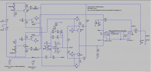
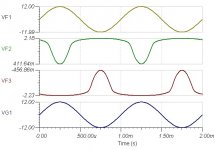
Attached the updated circuit and some simulation results. Please note the harmonics where derived from a more extensive simulation, which includes a switching stage with IRFP4668.
In the mean time I have settled a new adjustment which is fitting mostly my taste.
It has a comfortable idle switching frequency around 320kHz, good step response and bandwidth around 80kHz.
Harmonics at 400W/2R are in the -80db range, means further optimization by simulation would be completely meaningless, because in this range simulation and reality typically differ already pretty much.
Output voltage ripple is slightly below 500mVrms during idle.
No lunch for free.
These selfoscillating topologies are a tight knot in it self. No matter what you change, all other parameters change as well. Swichting frequency, loop gain, carrier shape, output ripple, step response...
Achieving overall good results with 320kHz does consequently lead me to a design with higher output filter inductance. 18uH.
Ok, that's not really high and for ripple current load of the e-caps this is even fortunate .
The downside of this higher inductance value is that it impacts the physical size of the output inductor and it also limits the power bandwidth of the amp.
The new adjustment has a bandwidth of 80kHz, but the high filter inductance is limiting the -3db power bandwidth to approx 24kHz (into 2R), which is just acceptable. Well, my intended MKP2 filter caps will also be close to melt down (at least running beyond spec), when applying something like 20kHz with full power as continuous load...
Attached the updated circuit and some simulation results. Please note the harmonics where derived from a more extensive simulation, which includes a switching stage with IRFP4668.
Attachments
Hi Nigel,IR do a 1.7KW amplifier project using IRs2092 and gate buffers to up the gate drive.
thanks for pointing to IRaud9.
Nevertheless I am of a similar opinion like workhorse.
- Pre filter feedback
- Triple paralleled MosFets
- Pure marketing numbers regarding power. They specify 1.7kW from +/-75V rails, which is poddible only with a perfectly regulated PSU - no sagging. And even then they have to go into clipping to achieve the power.
...hoping that I will not experience bad drawbacks during the real build and end up similar as IR...
Up to now I am heading for higher performance (faster and mostly load independend step response) and realistic power spec.
I am targeting 1kW/2R or bridged 2kW/4 from +/-80V rails, this allows to derive the specified power with realistic rail sagging.
Theoretically with hypex supplies it should end up in 1200W/2R or 2400W/4R bridged.
Brilliant, the threshold could be set very easily thru symmetric current sources/mirrors.
Here is a TINA SPICE sim of an opamp with symmetric voltage controlled current sources. The Zener diodes clamp the VCVS so they only change the output current when the output signal approaches the rail. With suitable component values, something similar to this might be able to provide the upper and lower threshold voltages for my 'Window Comparator plus S-R latch' acting as the PWM modulator.
Attachments
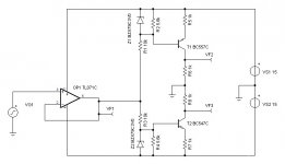
The op-amp is only there to provide a suitable sine-wave signal to demonstrate the concept, but I think that a similar pair of voltage controlled current sources could monitor the output of a class-D amp to provide the threshold voltages for the comparator.
If the window comparator technique can work with only changing one of the threshold voltages at a time (according to if the output waveform was approaching the +ve or -ve rail), then the voltage outputs from my simple circuit above might be able to be used directly.
If the window comparator technique can work with only changing one of the threshold voltages at a time (according to if the output waveform was approaching the +ve or -ve rail), then the voltage outputs from my simple circuit above might be able to be used directly.
.... but I think that a similar pair of voltage controlled current sources could monitor the output of a class-D amp to provide the threshold voltages for the comparator.
Nice ... have a look to Q9 and Q10 in posting #3.
They form a pair of current sources, which are monitoring the output of the class D amp.
Main difference is that I had chosen to run the BJTs in common base connection, because I do not need high gain in these controlled current sources, but appreciate linearity and speed.... and for my method of directly controlling the modulator thresholds with Q7 and Q8 also the signal polarity was fortunate.
Brilliant, the threshold could be set very easily thru symmetric current sources/mirrors.
Here is a TINA SPICE sim of an opamp with symmetric voltage controlled current sources. The Zener diodes clamp the VCVS so they only change the output current when the output signal approaches the rail. With suitable component values, something similar to this might be able to provide the upper and lower threshold voltages for my 'Window Comparator plus S-R latch' acting as the PWM modulator.
Exactly....


... have a look to Q9 and Q10 in posting #3.
They form a pair of current sources, which are monitoring the output of the class D amp.
Main difference is that I had chosen to run the BJTs in common base connection, because I do not need high gain in these controlled current sources, but appreciate linearity and speed.... and for my method of directly controlling the modulator thresholds with Q7 and Q8 also the signal polarity was fortunate.
Yup, could be done with CB//FC also.
For PCB layout I am using KiCad.
Attached the schematics, with the status of today.
Typically they will evolve a little bit further during layout work.
...and of course later again, when reality strikes back..
Besides the protections of the IRS, the design contains overvoltage protection and overtemperature protection.
Speaker protection is not included. There are tons of circuits around and personal taste is pretty different (traditional relay vs MosFet relay..).
Discussion on schematic is opened...
Attachments
Hi Tom,
I see four advantages of the IRS20957 vs IRS2011:
-Floating input stage, which allows direct drive from the comparator without level shifter inbetween.
-No need of inverted drive signals
-Convinient dead time adjustment
-Overcurrent sensing
But there are also downsides:
-Imperfections in the layout and snubbering can easily cause oversensitive shut downs (...let's hope that I'll get that right also for the fat TO-247 and the high power...)
-Range of possible dead time is not really wide
Blocking diodes:
You mean a shottky in series with the MosFet (for blocking currents through the body diode) plus a fast freewheeling diode across MosFet+schottky?
- Home
- Amplifiers
- Class D
- SystemD_2kW, any interest for an open design?