Dear John,
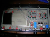
May I call you John? You can call me Kevin. I've sent you two photographs. The first is of the complete top of the board. In the second photo You can see where I've removed one leg of what I think is a small cap. (Sorry about the quality, its not a great camera.) Across this component I was finding the different voltage. Approximately 6 volts less than across the other identical parts. What I found when I disconnected it was the DC voltage on the input side at the RCA jack channel 2 disappeared. However the DC voltage for the output RCA low pass channel 2 is still there.
Have you found a technician that can help us? Or should I continue on my own?
As always, thanks for any help you can provide, Kevin
Attachments
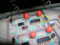
Kevin, the part you circled is a two terminal fet based current source. Can you read the number on it? It is important. The 14 pin device is a 4 matched complementary transistor set made by Motorola, starting with MPQ The 8 pin device is a fet pair not made anymore, but another part can be substituted. First, let's find the part number on the current source.
Hi John,
The part number on the fet is E506 7835. There are (4 )10D CO, or 100 CO caps? There are (16) 47-20 ++2 tantalum caps. The large OP amps are MPQ6600 A. Ther are more numbers but I need a magnifying glass to read them.
If I have DC where I shouldn't have doesn't sound like a bad capacitor?
Kevin
The part number on the fet is E506 7835. There are (4 )10D CO, or 100 CO caps? There are (16) 47-20 ++2 tantalum caps. The large OP amps are MPQ6600 A. Ther are more numbers but I need a magnifying glass to read them.
If I have DC where I shouldn't have doesn't sound like a bad capacitor?
Kevin
The MPQ devices are NOT op amps. They are 4 matched transistors, 2 npn and 2 pnp. This is what makes them difficult to replace. It doesn't really sound like a bad cap, but a bad active component. The caps are either Mylar coupling caps, film filter caps, or tantalum bypass caps, that usually are just for the power supply decoupling.
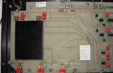
I love my ACS-1 and unfortunately, it seems to have developed a problem. Upon powering up, the power indicator seems dim and there is some distortion on one channel. After a few minutes, the light brightens up and all is well.
Is this a PS cap(s) going out or some other malady?
Also, mine has had a "Revision C" done to it. Was this a fix for bad traces or a performance modification?
I looks like these are close to un-fixable and I will be sad when it finally has to be retired.
Thanks, amt
Is this a PS cap(s) going out or some other malady?
Also, mine has had a "Revision C" done to it. Was this a fix for bad traces or a performance modification?
I looks like these are close to un-fixable and I will be sad when it finally has to be retired.
Thanks, amt
Attachments
Well, it sounds like something is 'going out' or you might have a bad physical connection somewhere. You should check the power supply voltages as it is coming up, to see. Tighten any mechanical connection and DeOxit anything you can. You can sometimes find a bad external cap by hitting it with 'Freeze Spray'. the thermal change will bring it on, or fix it. You don't have to replace any external power supply cap with exactly the same thing. Even an electrolytic cap will be OK. IF it is the power supply module, then you might have to find one to replace it. Alternate modules that have the same pin-out should exist, being made by someone, somewhere.
Hi John,
Your suggestion that it was more likely to be an active component got me thinking. Instead of looking on the supply side I started at the channel 2 input and low pass output, (where the DC voltages were first found) and followed the voltages back through the crossover. I arrived both times at an 8 pin transistor. LF 356N. The corresponding channel 1 transistor showed about 12.8 volts dc on two of its pins. The channel 2, various dc voltages on most of its pins. I replaced the transistor and the dc is gone from both the input and the output. As soon as I put it in a system and test it I'll write back with the results. But I feel confident it will be fixed. Thanks again, talk to you soon.
Kevin
OPA134 (OPA2134) is nice.Please be careful. You are replacing a fet input IC with standard pin configuration. Pin 6 is the OUTPUT. You can replace it with another fet input IC, such as an OPA134 if you wish.
- Not too expensive -- we are not all made out of money
- Quite good performance data, not really bad at anything
- FET input, with less worry about DC-offset
- Good current output drive >=35 mA
- Stable from Gain = 1, not often oscillation problems
All this together makes a very good choice for everyday DIY folks.
And no wonder it is very popular for audio
")
Hey All,
Ignorance is bliss, or "Insanity is a small price to pay for happiness." Pin 6? I didn't no they had numbers. I just assumed the dot on the one side was a marker and I put the new transistor in the same as the old one. I've never de-soldered parts from a board. but it seemed to go smoothly.
I didn't want to risk anything really valuable or powerful. So I used my old Advent receiver putting the crossover between the preamp out/main in with some cheap speakers. This way I could only test the low pass and the high pass independently. But everything seems to work just fine.
I got the transistor from Digikey, I think it cost a dollar something. College prep school, four college degrees and I still work as a mechanic. Wish I had become an electronics tech to start with. Its a lot more interesting and much cleaner than working on cars.
Thanks John, Kevin
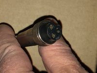
I recently got an ACS-1 without the power supply. I have a suitable supply, but would like to make it neat in an enclosure. So I will purchase a panel-mount jacket for the power- supply plug and want to make sure I get the right one. Can someone steer me to it? It’s got 3 conductors but I can’t identify it for certain. Thanks in advance!
I'm not sure I understand. My Symmetry has the power supply within the chassis. In fact the power transformer is mounted on the circuit board. This is a very low profile transformer that I've heard is no longer available. I suspect your transformer may have failed and someone built an outboard supply to replace it. Just guessing but it might be that one wire is for the positive supply another for the negative, and the third the ground.
You are in trouble! You will have to trace which pins are +15, -15, and ground. The early Symmetry xovers had an internal +/-15V power supply, the later units must have something similar, but you are going to have to find out which pin is for what by looking at the polarized caps inside and noting their polarity connecting to the trace that goes to each pin that is the respective voltage. It is not that hard, but you have to be careful.

You are in trouble! You will have to trace which pins are +15, -15, and ground. The early Symmetry xovers had an internal +/-15V power supply, the later units must have something similar, but you are going to have to find out which pin is for what by looking at the polarized caps inside and noting their polarity connecting to the trace that goes to each pin that is the respective voltage. It is not that hard, but you have to be careful.
I am happy to announce that I have succeeded! The pandemic has given me opportunities to get to projects (not all of them!) and I managed to trace the pins and wire it up! Thank you for your help, and your work on a great crossover years ago.
- Status
- This old topic is closed. If you want to reopen this topic, contact a moderator using the "Report Post" button.
- Home
- Amplifiers
- Solid State
- Symmetry acs-1