Having trouble submitting the attachment
If it doesn't work this time try this:
http://www.aaroncake.net/Circuits/supply3.gif
If you don't have all the rest of your parts already you
may want to try this variation:
http://www.aaroncake.net/Circuits/supply3.asp
If it doesn't work this time try this:
http://www.aaroncake.net/Circuits/supply3.gif
If you don't have all the rest of your parts already you
may want to try this variation:
http://www.aaroncake.net/Circuits/supply3.asp
Attachments

Ok, seems to have came out same size either way.
The links may be more viewer friendly.
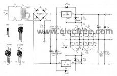
Another variation of pretty much the same thing but
rather than showing the line going from the secondary
center tap directly to the caps it is using the ground symbol.
The caps are also tied to ground same way.
Just another way of doing schematics
In any case no matter what schematic you use "PAY CLOSE
ATTENTION TO THE POLARITY ON YOUR CAPACITORS"!!!!!
Wire them with the + and - reversed and they can let
out a good boom as well as the resulting noxious chemical fumes!
The links may be more viewer friendly.
Another variation of pretty much the same thing but
rather than showing the line going from the secondary
center tap directly to the caps it is using the ground symbol.
The caps are also tied to ground same way.
Just another way of doing schematics
In any case no matter what schematic you use "PAY CLOSE
ATTENTION TO THE POLARITY ON YOUR CAPACITORS"!!!!!
Wire them with the + and - reversed and they can let
out a good boom as well as the resulting noxious chemical fumes!
Attachments
I definitely want to jumper transformers pins 9 and 10 together? Looking at the Velleman diagram, it looks like I'm supposed to have four wires from the transformer.
Possibly they're bridged on the PCB board itself?
I guess my real question is, which pins have should have voltage going in, and which pins have voltage going out?
An externally hosted image should be here but it was not working when we last tested it.
Possibly they're bridged on the PCB board itself?
I guess my real question is, which pins have should have voltage going in, and which pins have voltage going out?
OK, I'm assuming you defineately ordered the Velleman kit?
If that is correct and you didn't make your own board design,
either Pin 7 or Pin 12 goes to SK1 and the other to SK2.
(Doesn't matter because it is still AC at this point.)
Ex: If you have pin 7 going to SK1 then pin 12 goes to SK2
or If pin 12 goes to SK1 then pin 7 goes to SK2.
Pin 9 and Pin 10 can either be wired with 2 separate wires
that go to the terminals that are labeled 0- between SK1 and
SK2. (It does not matter which one goes to the top 0 or bottom
0 as you notice they tie together at GND anyway.
You could also tie 9 & 10 together on the tranny and run
a single wire to either one of the 0's.
I would defineately attach the green ground wire or the middle
ground terminal (I don't know if your using an IEC receptacle
or just a 3 wire cord with the loose wires on the end?) to the
chassis at least. I think it may be optional to connect it to the
board. You would want to connect it to the one of the two
terminals marked "0" between SK1 and SK2 if you do.
Reason I say optional is it may create ground loops depending
on the rest of your system (equip. + how it's all hook up).
There are several other options to include CR networks, thermistors, etc. that tie the board softly or freq. dependent
to ground. I've also seen schemes using a small switch to
attach it signal completely to chassis, isolated through resistor,
capacitor, or switchable to completely float.
Don't really have the right software to draw up a switched
schem. at the moment.
Anybody else out there have a schematic handy to post?
I don't have a chassis for it yet, actually. It's all just sitting on my desk next to the turntable. I tested it out with the Bugle preamp last night and it all worked fine.
The turntable ground wire is connected to the Bugle ground screw, but the Bugle isn't grounded to anything, the turntable is an old BIC 960 that uses a two prong power cord, and the power supply isn't grounded to anything either.
The turntable ground wire is connected to the Bugle ground screw, but the Bugle isn't grounded to anything, the turntable is an old BIC 960 that uses a two prong power cord, and the power supply isn't grounded to anything either.
- Status
- This old topic is closed. If you want to reopen this topic, contact a moderator using the "Report Post" button.
- Home
- Design & Build
- Parts
- Symmetric supply or dual supply?