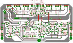
pcb for SYMEF using mpsa92
here is the pcb for SYMEF.dc offset lowest is 3.9mv. and used as output transistor is 2sc5359 and 2sa1987.
turn trimmer clockwise to set idle current at minimum.and do not operate the amplifier using single pair output transistor.
r27 and r35 should be 1 watt using a supply of 50volts.enjoy")
idle current is set to 46mv across two emitter resistor
regards,
joel
here is the pcb for SYMEF.dc offset lowest is 3.9mv. and used as output transistor is 2sc5359 and 2sa1987.
turn trimmer clockwise to set idle current at minimum.and do not operate the amplifier using single pair output transistor.
r27 and r35 should be 1 watt using a supply of 50volts.enjoy
idle current is set to 46mv across two emitter resistor
regards,
joel
Attachments
Last edited:
reasons....
turn trimmer clockwise to set idle current at minimum.and do not operate the amplifier using single pair output transistor
why I said this its because my first attemp it blew the power transistor and one resistor because I forgot to set the trimmer at minimum and use only one pair of transistor.And bought that at a very low price and for sure it is fake.As you can see in his thread I'm still waiting for the delivery of transistor from a reputable supplier.
And my second attemp as you can see in the picture I have used a sanken transistor again it is only one pair and that time I have measured the idle current it was more than 600mv.and was able to adjust the idle current to about 46mv.(Now I know that sanken transistor is very rugged.
)And able to listen at this amp.
In Harisson schematic it was designed to operate at 40v but my supply is 52 volts dc.Surely that high supply it needs two pairs of power transistors.Two pairs of power transistors even you committed the same mistake I made, I'm sure It will have a chance of 100% of survivability.
I dont want to be exaggerated about SYMEF amp.I have already said it and experienced it.Unless you are not willing to try SYMEF AMP.Those questions and craving in your mind will remain forever.I have successfully build his amp.and listen above normal listenning it has no issue and it is stable.
Sounds is very, very good also.
Regards,
joel
sorry...
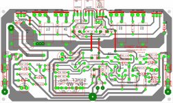
I have noticed that in picture one of the differential transistor is missing.its because it was designed to mount at the bottom of pcb which it should not be.And the pin configuration is wrong.this happens when I mirrored copy the other transistor.
In this post I have corrected the layout.
Regards,
joel
p.s.
The pcb layout I have used is designed for bc556 but used bc557 which increased the dc offset.(bc556 is not available at my supplier)I end up using mpsa92 as my differential transistor but thermal coupling is impossible because they are facing in opposite.
I have change the layout of the differential transistor designed for mpsa92 so tying it is now possible.
correct pcb layout for bc556 is in post 134
Attachments
Last edited:
yes you are right...
but during that time im using bc557 in my last thread Harrison said that his glad I debugged that high dc offset.using mpsa92 check theres a reading 4.4mv and check the facing of differential transistor.
I have included the picture of 36mv but thats previous just to show the measurement of the amplifier.
about the vr before I installed it I have set it in middle I think 500ohms.thats why Im confident.you know I do really like the way harisson design this. It takes how many turns to lower the idle current which is very good when amp.is configured in complementary feedback.but it is emitter follOwer and very easy to attain 46mv.
regards,
drowranger
Drow,
you are impossible.
the DX Threads show pics of a simple way to Thermally couple a pair of LTP To92.
You blew up your output stage because you did not use a bulb tester, not because you made a mistake in understanding what way to turn a VR.
but during that time im using bc557 in my last thread Harrison said that his glad I debugged that high dc offset.using mpsa92 check theres a reading 4.4mv and check the facing of differential transistor.
I have included the picture of 36mv but thats previous just to show the measurement of the amplifier.
about the vr before I installed it I have set it in middle I think 500ohms.thats why Im confident.you know I do really like the way harisson design this. It takes how many turns to lower the idle current which is very good when amp.is configured in complementary feedback.but it is emitter follOwer and very easy to attain 46mv.
regards,
drowranger
Attachments


If I had assembled the amp.and my only mistake is that the pot is set at maximum and the bulb is connected the amp.will this bulb tells me that the amp has a problem?
regards,
joel
Yes, you can save your amp.
Through my experiance, I connect incandescent bulb (60W) in series to both +/- rail input. When first power up the bulb never lights up or glows slighty. BUT when the glow starts increasing, I quickly turn of the power. During this period, the bulb is resisting high power supply and amperage to the amp.
I will disconnect and check for faults.
Regards.
A bulb tester is normally in the mains side feeding the primary of the transformer.
In this position it acts as an indicator of current flow and as a current limiter.
If the bulb lights up then the transformer is trying to draw lots of mains current.
If the bulb glows then it tells you that the transformer is drawing a low mains current.
If the bulb does not glow then it tells you that the mains current is very low.
Start with a low wattage tungsten filament bulb. Prove that you have wired up the equipment properly.
The bulb raises the source impedance feeding the transformer.
Worse, the impedance varies very much with load.
But the protection offered by the bulb during start up is lost once the main smoothing bank is charged up.
The energy stored in the caps is enough to blow up any device if you stick a probe in the wrong place.
There is no advantage to keeping the bulb in place while you bias up the amplifier and certainly NEVER to operate the amplifier.
>29.999k buildersneeded
Looking for members who are willing to drive the state of the art by building this amplifier and providing feedback. Your ears are very much needed.
Will your search for the perfect amplifier stop here ? What makes the symef soo special or not. Join the club today and do checkout the website.
all the best
Harrison.
Hi OnAudio!
I am interested but there are opinions that symef in instable. Could you post a few pictures how it behavies with capacitance load or other measurings?
Thank you in advance!
Harrison, have you ever built, measured or heard any of the audio projects that you so keenly promote and want others to spend money and effort on to see if they actually work?
Padamieki, there are many amplifiers on this site that are excellent and works. Why not try a proven working design. Look at SSA for instance or any of APEX offerings.
Padamieki, there are many amplifiers on this site that are excellent and works. Why not try a proven working design. Look at SSA for instance or any of APEX offerings.
Haven't gone through the whole thread, but the folded cascode second stage would be much better if referenced to ground, not -supply.
This can be done by loading LTP transistors with current sources and referencing folded cascode common base transistors to minus several volts versus GROUND.
This way PSRR can be improved even by 20-30dB leaving the transfer functions pretty much untouched.
Also the current mirror can be made wilson type at minimum expense improving the things further.
Hi Pawel,
The amplifier is stable. If you are looking for some excitement this is the right thread. It even gets better, we will be with you all through the construction process and wait it gets even better you get to tell the world your experience. This amplifier has over 10,000 hours put into it
Please do join us and welcome to the club.
kind regards,
Harrison.
a short story
As the African sun was rising and warming the bowels of the earth. Lions were stretching themselves ready for another day a day full of great expectations. Nico had just had breakfast, he was longing for this day...on this day he would get to plug in the SYMEF and listen. He had finished the project late at night.
When the first tones came through, Nico sat up, paused and took a deep breath, he listened a long time. Nico finally moved over to his laptop and logged onto diyaudio and started typing ...................................................................
....to be continued
I like amplifiers made like that, i.e. moderate feedback at LF and constant up to 20kHz, preferably with foldd cascodes.
They do sound very good, even if they are not outstanding specs-wise
However their drawback too often lies in PSRR, the reason is the first stage does not generate enough gain for PSRR to vanish in further stages.
One trick I like is described above, another (better) is to add some more fancy cascodes.
Schematics:
Attachments
- Home
- Amplifiers
- Solid State
- SYMEF amplifier