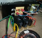
Ok, I have built 1 channels worth of electronics and am testing. I have about 15,000uF of capacitance before each regulator. The regulators are set to produce +/-30V output (reality +29.7/-29.9).
I have been testing the regulator board on its own. I had issues with it oscillating with anything over 1A load but added capacitance seems to fix this. Oscillation was only less than 1V anyhow. Otherwise outputs were clean.
I have it now connected to the amplifier and bias set to produce 1W into 8ohm class A. Heat is pretty manageable. Regulators are very cool, output transistors I can keep the back of my finger on and overall heatsink is just "warm".
I have a slight concern with oscillation still though. I noticed when looking at the output from the amp with my scope that there was a high frequency (my scope is cheap and only has 0.5uS max speed, but the waveform is there and appears on the screen mabye 40 times). I found the same frequency on the output of both + and - regulators. Thing is, it's only about 5mv peak level at either point. Need I be at all concerned about this? I will need more testing to check it won't get worse with higher outputs.
Attachments
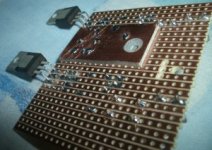
Have the other channel nearly ready and it seems to be working. Haven't set up bias for it yet. On this regulator I used a piece of copper clad board for the ground area. It seems to work very well (the other used lts of solder and bare wire, kinda messy). I get no change in noise or voltage when a 1.4A load is added, it remains below 5mv of noise which is decent.
Should be ready to go soon. Back panel needs sorting primarily, along with internal cabling. Also, the transformers are switched by relays; would it be ok to put the switch between the twin primaries? It saves wiring and I can't see it being a problem (ie. switch is between purple and grey wires). Grounding this could be a nightmare though
Should be ready to go soon. Back panel needs sorting primarily, along with internal cabling. Also, the transformers are switched by relays; would it be ok to put the switch between the twin primaries? It saves wiring and I can't see it being a problem (ie. switch is between purple and grey wires). Grounding this could be a nightmare though
An externally hosted image should be here but it was not working when we last tested it.
Attachments
One mod I made to the original design was changing the input long tailed pair tranzistors to 2sk170B. It's really a worthwhile change. (Does nothing to do with the bias current increase)
A little OT,but did you change any resistors or just swap them in?
Ok.Ryssen, you just have to swap them. No further modifications needed. Just make sure you pair them and the Idss is in the 5-6mA range for best liniarity.
Bit held up now with a stupid problem, one of the little hex bolts sheared off . I reached the bottom of the thread and didn't realise and the head just twisted off. I have threaded a nut onto the stub sticking out and have sealed the thread with epoxy resin, hopefully when it sets I can use a spanner to remove the stub; not too optimistic though.
Otherwise it'll have to stay there and me add a clamp mount accross the semiconductor (actually not a bad way to do it but annoying extra work). Waiting for resin to dry now i'm afraid anyhow
. I reached the bottom of the thread and didn't realise and the head just twisted off. I have threaded a nut onto the stub sticking out and have sealed the thread with epoxy resin, hopefully when it sets I can use a spanner to remove the stub; not too optimistic though. Otherwise it'll have to stay there and me add a clamp mount accross the semiconductor (actually not a bad way to do it but annoying extra work). Waiting for resin to dry now i'm afraid anyhow
Ok, the resin didn't work but I managed to drill it out and re-tap the thread. Have now near enough finished this amp. Some pictures
Need to prepare top lid, think I'll need to drill ventilation holes for this one. The bias is 320ma on each channel, heat is quite manageable like this, the unit is just "warm" all the time.
Not done any serious listening or full testing yet but it does work and without really being analytical the sound is fine. It is designed for treble, I don't think these regulators allow for the large current peaks required for powerful bass, however ran full range the bass is actually still very good (only used at low levels so far mind). Initially the treble is sounding very clear and present but not harsh/false so this is promising
Wasn't too impressed to find that big print on my aluminium, underneath the protective layer. Lucky it's on the bottom of the amp but I fear there could be more on my others since they still have the layer on . The round 3 pin connector is for remote switching; there are 2 relays in this amp and each transformer will be switched individually to reduce startup load (they're only 160VA each). Possibly not ideal but the relays connect the 2 primaries together rather than isolating the live (saves wiring), either way the whole system will be isolated overnight or when left etc. There are actually 9 fuses in here too
An externally hosted image should be here but it was not working when we last tested it.
An externally hosted image should be here but it was not working when we last tested it.
An externally hosted image should be here but it was not working when we last tested it.
Need to prepare top lid, think I'll need to drill ventilation holes for this one. The bias is 320ma on each channel, heat is quite manageable like this, the unit is just "warm" all the time.
Not done any serious listening or full testing yet but it does work and without really being analytical the sound is fine. It is designed for treble, I don't think these regulators allow for the large current peaks required for powerful bass, however ran full range the bass is actually still very good (only used at low levels so far mind). Initially the treble is sounding very clear and present but not harsh/false so this is promising
Wasn't too impressed to find that big print on my aluminium, underneath the protective layer. Lucky it's on the bottom of the amp but I fear there could be more on my others since they still have the layer on
. The round 3 pin connector is for remote switching; there are 2 relays in this amp and each transformer will be switched individually to reduce startup load (they're only 160VA each). Possibly not ideal but the relays connect the 2 primaries together rather than isolating the live (saves wiring), either way the whole system will be isolated overnight or when left etc. There are actually 9 fuses in here too the on off switch leaves both the Live and the Neutral connected. Naughty!Dr.EM said:there are 2 relays in this amp and each transformer will be switched individually to reduce startup load (they're only 160VA each). Possibly not ideal but the relays connect the 2 primaries together rather than isolating the live (saves wiring), either way the whole system will be isolated overnight or when left etc.
clearly label the switch as "standby" or some similar word that does not risk a technician/probing hobbiest.
Theres actually no switch on the power amp itself (any of them), they will be sequentially switched on via the preamp but yes, when that is complete I will be sure to label the start up button "standby". All of this equiptment will likely be connected to one of these:
http://www.dv247.com/invt/47520/
and it's front panel switch will be used to actually switch eeverything off (including the preamp itself). Hopefully if anyone over than me ever felt the need to open one of the poweramps they would isolate it by pulling the IEC out anyway.
http://www.dv247.com/invt/47520/
and it's front panel switch will be used to actually switch eeverything off (including the preamp itself). Hopefully if anyone over than me ever felt the need to open one of the poweramps they would isolate it by pulling the IEC out anyway.
Ok, drilled the top panel now. I know its probably not the nescecary because most parts are thermally coupled to the heatsinks/body but it might be best since this amp runs quite warm. I know they are of limited effectiveness without holes in the bottom too.
The writing came off with acetone no problem, there was some on the top too.
Just need a front panel now
An externally hosted image should be here but it was not working when we last tested it.
The writing came off with acetone no problem, there was some on the top too.
Just need a front panel now
- Status
- This old topic is closed. If you want to reopen this topic, contact a moderator using the "Report Post" button.
- Home
- Amplifiers
- Solid State
- Symasym biased for class A