Setting the bias (DUMMY ALERT)
I'm pasting together W-proof construction instructions for myself, just so I don't do something W-stupid. A couple of questions:
1) I believe that 150ma was the preferred AB bias level, but that going more towards A produced better sound. Is this correct, and what are the theoretical limits on both sides of 150ma, given a reasonably efficient heatsink?
2) At what points (across which component) does one measure the bias?
Thanks. I'll probably have more questions later, and will post the final draft of the instructions for your review. I'll also include pictures of my monoblocs and my final BOM (no dangerous mods, just a few experiments with different component brands).
George
BTW, I've been plodding through both the original and the sequel thread, and I'm amazed at how much high-quality work from high-power minds went into the sym-a-sym's design and testing. Sum o' y'all boys is shur-enuff smart. And I'd really like to spend some time with Carlos (especially if he brings his daughters and introduces me to Rosalinda). What a delightful person. Would that the US had a person like him as the Decider. Oh well, I suspect we've got the leadership we deserve. I'd still like to drink beer, eat sausages and swap tales with you, Carlos.
Hi George,
I bias Symasym using my PCB version and BOM at 25ma. That's 10mv across both 0.2 emitter resistors. I found that anything above that THD wise makes no difference at full power into 8 ohms. Sound wise it could, haven't tried it. Try it but make sure you have a suitable heatsink.
Best regards,
Al
I bias Symasym using my PCB version and BOM at 25ma. That's 10mv across both 0.2 emitter resistors. I found that anything above that THD wise makes no difference at full power into 8 ohms. Sound wise it could, haven't tried it. Try it but make sure you have a suitable heatsink.
Best regards,
Al
Thanks, Al.
My cases are almost done. And it only took me four months! I'm glad this is my last pair of DIY monoblocs. The boards will be a cinch after this.
BTW: that's a really nice board - compact, well-laid out, extremely short traces.
And nicely executed, Ryssen.
George
My cases are almost done. And it only took me four months! I'm glad this is my last pair of DIY monoblocs. The boards will be a cinch after this.
BTW: that's a really nice board - compact, well-laid out, extremely short traces.
And nicely executed, Ryssen.
George
AAK said:Hi George,
I bias Symasym using my PCB version and BOM at 25ma. That's 10mv across both 0.2 emitter resistors.
Al
It's to little. In fact, you should have at least 15mA over one Re but no more than 25mA. This is true only for emitter follower output stage.
Make a search in the forum about "gm doubling".
http://www.diyaudio.com/forums/showthread.php?s=&threadid=86528&highlight=
roender,
After reading your original post on bias, your bias is only 5ma higher than mine. Shouldn't make any difference at all in sound quality or distortion. I guess it was determined that significantly higher bias like 150ma improves sound quality. I'll try it out and report back.
Al
After reading your original post on bias, your bias is only 5ma higher than mine. Shouldn't make any difference at all in sound quality or distortion. I guess it was determined that significantly higher bias like 150ma improves sound quality. I'll try it out and report back.
Al
AAK said:roender,
Based on the link you provided I assume that your bias recommendations are to improve sound quality. Because from my testing increasing the bias beyond my recommendations will not improve THD.
Regards,
Al
You can not see any improvement in THD-1kHz between 10mV and 15mV Re voltage, but it make a huge difference in THD-20Khz and specialy in high order harmonics.
All the best,
Mihai
Ahh,after that you are only going to build stereo amps?I'm glad this is my last pair of DIY monoblocs.
")

Hi Ryssen,
Nop, I can assure you that your not blind, but I may be.
I went over the BOM three times so hopefully this one will be the last. I did change the format a little keeping the parts with same value together to make it easier to follow especially when ordering.
And added a new part from OnSemi for D1,D2,D3,D4 thanks to SteveA. It's direct replacement for the IRF part and 25% cheaper. Also on the old BOM C10,C11 has a value of 0.1uF/63V, it should be 0.1uF/250V same as C23,C24.
Regards,
Al
Attachments
So far so good..(Bryan Adams)
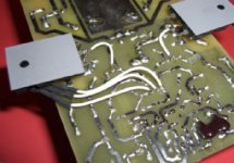
My heatsinks are just as high as the PCB´s,70mm.So to make it work I guess i have to do sommething like this..
For Q1 and Q2 I have soldered some sockets,so that when everything is working like it should I can try some J-Fets..
I bougt some matched smallsignal transitors for the fronend.
Now on to some boring case work..
An externally hosted image should be here but it was not working when we last tested it.
My heatsinks are just as high as the PCB´s,70mm.So to make it work I guess i have to do sommething like this..
An externally hosted image should be here but it was not working when we last tested it.
An externally hosted image should be here but it was not working when we last tested it.
For Q1 and Q2 I have soldered some sockets,so that when everything is working like it should
I can try some J-Fets..An externally hosted image should be here but it was not working when we last tested it.
I bougt some matched smallsignal transitors for the fronend.
Now on to some boring case work..
Ryssen,
Did you get any response to your question?
Ah ha!...found in a different thread:
MikeB offered:
Did you get any response to your question?
The output transistors 2sc5200-OQ/2sa1943-OQ Are there any bennfits sonical to use them compared to MJL21193/94 or MJL1302/MJL3281?I have lots of them.
Ah ha!...found in a different thread:
MikeB offered:
It depends on your taste, the MJL21193/4 sound very lovely, tubish like, the MJL3281/1302 sound very clear/hard, the SC5200/SA1943 very soft but clean. My Favourite is MJL0281/0302 (or MJW), they sound crystal clear and clean but no sign of hard sound
- Status
- This old topic is closed. If you want to reopen this topic, contact a moderator using the "Report Post" button.
- Home
- Amplifiers
- Solid State
- Symasym 5.3 "AAK model" builder's thread