Gyrator- it acts like a large, nearly ideal inductor. You can read all about it here: SYclotron Audio The Acheron: Electronic Crossover Design
Could Peter articulate what he found dissatisfying about his Sallen-Key crossover? I have a Sallen-Key crossover set up for LwR alignment I was intending to use to split between two amps, one feeding midwoof and one feeding tweeters. Crossover point was set for 5kHz. I put mine together using current souce-loaded source followers made out of PN4393 JFETs. I may try the Acheron design using JFETs with the same alignment and crossover frequency to get a side-by-side comparison of the two filter types.
I'm leaning toward a flexible modular preamp design using SMA input and output connectors so that I can easily swap various experimental components around, with one standard board size for RIAA preamp, one for line amp/buffer, and one for crossover filters. This is all in the sand state realm for now, but one could gin up something similar with tubes.
I'm leaning toward a flexible modular preamp design using SMA input and output connectors so that I can easily swap various experimental components around, with one standard board size for RIAA preamp, one for line amp/buffer, and one for crossover filters. This is all in the sand state realm for now, but one could gin up something similar with tubes.
Could Peter articulate what he found dissatisfying about his Sallen-Key crossover?
I wouldn't say that I was dissatisfied with the topology... more that the implementation wasn't good enough. My main issue was that I never got it quiet enough.
I didn't put a lot of effort into optimizing it, but on initial listening I didn't find it to sound any better than the passive xovers in the speakers (Klipsch's, if I recall). So I shelved it...
Pete


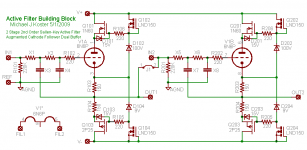
High open loop gain is not needed for Sallen-Key. I prefer a nice unity gain buffer block like an augmented cathode follower having high symmetric current drive capability.
I think something like this would be a good implementation of a Sallen-Key topology that would have very low distortion to give excellent performance for LR4 and other low-Q filters.
I think something like this would be a good implementation of a Sallen-Key topology that would have very low distortion to give excellent performance for LR4 and other low-Q filters.
Attachments
Hello,
Line level crossovers have an appeal. Getting the crossover elements from between the amplifier and the speakers seems to be a good idea.
Does the line level crossover need to be active? How about a passive filter at the output of the line amplifier followed by a cathode follower to each power amplifier. There have been many discussions in the RIAA realm. Could be fewer active parts with less added noise.
Dt
All just for fun!
How about a passive filter at the output of the line amplifier followed by a cathode follower to each power amplifier.
Passive Line Level XO (buffered or unbuffered). With just RC somewhat limiting in capabilities, but works well if those limitations fit your speakers.
What has been shown in post 77 is essentially an LC buffered (yellow) passive line level XO (red) with an active circuit emulating the inductor.
dave
Attachments
Yes, it does. You can only get the required slope with L and C (and at these impedances, the L would be enormous), so you substitute C and R and active stages to synthesise what you could have got with L and C.Does the line level crossover need to be active?
Your point about noise is valid, and the best place for the volume control is therefore after an active crossover. You now have the problem of ganging not just two controls accurately, but four or six. Stepped attenuators (IC or discrete) are a must.
Hello EC8010 and All,
I looked at the inductor values required for passive filters, yes they are huge. It does look like active filters are required if line level crossovers are desired.
Looking at the proposed designs in this thread there are many CCS devices used or at best the circuits are combination SS and Glass. Trying to stay away from the OpAmp sound with all the feedback has anyone built a Salas style 2SK170 discrete version of SS class A crossover. The simplistic 2SK170 crew publish test data with background noise levels as dark as the night. Thoughts?
DT
All just for fun
I looked at the inductor values required for passive filters, yes they are huge.
It would be nice to find a source for the inductors Marchand uses in the XM46. It thou suffers (i usederstand) from a 5k load at the output so it would still be advantageous to buffer the circuit,
dave
Looking at the proposed designs in this thread there are many CCS devices used or at best the circuits are combination SS and Glass. Trying to stay away from the OpAmp sound with all the feedback has anyone built a Salas style 2SK170 discrete version of SS class A crossover. The simplistic 2SK170 crew publish test data with background noise levels as dark as the night. Thoughts?
DT
All just for fun
I'm not following this.
How does the use of CCS and voltage follower devices with unity gain stages lead to "the OpAmp sound with all the feedback", and how does a SS shunt regulator alleviate it? Or maybe you're referring to a different "Salas" circuit?
Cheers,
Michael
Last edited:
hello,
I lumped several SS things in altogether. They may not all be equally guilty. OpAmps have huge open loop gain and if they are spooled up with unitary gain there is a lot of feedback. I have often used OpAmps and like them. Some of best friends are OpAmps. This time I am leaning towards Class A, Glass if possible. I also use IXCY 10M (whatever the part number) CCS devices and like the results. I am not sure what the IXCY CCS device is guilty of but it is SS. This is the however. If the circuit is half SS why not go all out and use all discrete class A SS. I would rather have all glass if it is quiet. I know that I am suffering from dual personality but that is ok. Line level crossovers have lots of parts and tend to be noisy. My all Glass vinyl to headphone system is dead quiet with the headphones on my head. All of the line level crossovers I have used from Rane Pro gear, Behringer DCX to DIY Rod Elliot OPAmp circuits They all have some degree of audible noise at the speaker cone. Could be hum buzz or hiss or all of it. Is there a way to make it quiet?
Is that more clear?
DT
All just for fun!
High open loop gain is not needed for Sallen-Key. I prefer a nice unity gain buffer block like an augmented cathode follower having high symmetric current drive capability.
I think something like this would be a good implementation of a Sallen-Key topology that would have very low distortion to give excellent performance for LR4 and other low-Q filters.
I like it. Modern semiconductors are very nice additions to vacuum veterans.
Hi Dual triode, I think you have missed the point of SY's circuit?? Whilst the opamp strictly speaking can't be said not to be in the signal path, it is configured in a shunt configuration, it is a completely different animal to a sallen key implementation. It is working as a simulated inductor, which for all intents and purposes, probably is closer to an ideal inductor than any passive component you are likely to be able to make.
If you haven't done so already have a read of Sy's acheron article on his web site") I imagine making an all tube gyrator circuit would be a little hard to pull off it would be possible perhaps using Nelson Pass' discreet opamps paper as a guide, but I shudder to think how many tubes you would end up needing just to do what that opamp is doing
I imagine making an all tube gyrator circuit would be a little hard to pull off it would be possible perhaps using Nelson Pass' discreet opamps paper as a guide, but I shudder to think how many tubes you would end up needing just to do what that opamp is doing
The circuit shown has a 2nd order butterworth slope, and for all intents and purposes could be built substituing a 204mH inductor for the U1 opamp and supporting circuitry as Planet 10 pointed out.
Tony.
If you haven't done so already have a read of Sy's acheron article on his web site
I imagine making an all tube gyrator circuit would be a little hard to pull off it would be possible perhaps using Nelson Pass' discreet opamps paper as a guide, but I shudder to think how many tubes you would end up needing just to do what that opamp is doing The circuit shown has a 2nd order butterworth slope, and for all intents and purposes could be built substituing a 204mH inductor for the U1 opamp and supporting circuitry as Planet 10 pointed out.
Tony.
It looks like the simple grounded gyrator circuit could be done with an opamp or a good fet or VT-based follower circuit. It's very simple for the high-pass circuit, as one is using the inductor with one end grounded, allowing use of the gyrator circuit in its most basic form. If you want a low pass circuit, it gets more complex, as you need a floating gyrator circuit. Another possibility would be to subtract the high pass function from the original signal to get the low pass. I'm following this thread to see what develops, but I'll most likely try my jfet follower Sallen-Key crossover first, as the circuit is already built.
I imagine making an all tube gyrator circuit would be a little hard to pull off
This couple of filters can be reconfigured to a couple of very clean gyrators, if high Q is not required: http://www.diyaudio.com/forums/tubes-valves/161644-sy-pete-millett-crossover-9.html#post2220929
Hello wintermute,
I believe I get the point. The Ideal Gyrator originated by Tellegen in 1948 is a simulated element where equivalent L = C * R^2. Tellegen’s work precedes Sallen and Key by 7 years. The idea is to replace passive iron with active circuits. Too bad we have forgotten Tellegen’s name. The original Tellegen gyrator was built with a tube.
I am with you I would like to see the OpAmps out and glass in. Hey It’s not my project, just fun stuff to follow. I will keep reading the thread.
DT
All Just for fun!
OK no probs DualTriode probably a case of me not getting your point I've read that gyrators can be made with a single transistor (so I guess no problem with a single tube) but I'd also read that the performance was not as good as what can be had with an opamp. I haven't tried (I did search for a transistor gyrator circuit myself but failed to turn up anything satisfactory, I certainly don't have the knowledge to build one myself) so decided I'd stop being a purist and accept an opamp used in a shunt config. My design (still yet to be built) was inspired by SY's though I will be using Pass DC B1's for the buffers not tubes.
Tony.
I've read that gyrators can be made with a single transistor (so I guess no problem with a single tube) but I'd also read that the performance was not as good as what can be had with an opamp. I haven't tried (I did search for a transistor gyrator circuit myself but failed to turn up anything satisfactory, I certainly don't have the knowledge to build one myself) so decided I'd stop being a purist and accept an opamp used in a shunt config. My design (still yet to be built) was inspired by SY's though I will be using Pass DC B1's for the buffers not tubes. Tony.
- Status
- This old topic is closed. If you want to reopen this topic, contact a moderator using the "Report Post" button.
- Home
- Amplifiers
- Tubes / Valves
- SY/Pete Millett Crossover