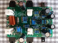
Here are my measurements, in bold on Thimios's ones, with R20 lifted.
Quite similar, except between Q1 and Q2 emitters (and across R18 and R19, which is not suprising owing to the supply voltage difference : 24.9 against 21V).
Despite this bias issue, music is coming through the amp, difficult to assess the quality as mono only and not on the final speakers. Doesn't look distorted. Quite some power available.
No component heating abnormally, even R9 0.5W.
Attachments
Y
re the NJW devices - I have not used these personally, so cannot offer a circuit to use the in built sense diode.
the simplest way to use the thermal track diodes is to split the current the diode current flows through adjustable resistor that sets bias. That gives a rather stable idle current even after junction temp peak 100 °C. But another problem is the matching of the 1381/3503 pair... 2SC3503 is very low in stock. No wonder really as this type is sort of last offspring of those CRT drivers color TV CRT .. they are gone forever. Thus I use a matched pair 1112/2592 which has Cob 30pF fT 200 mHz. I don't have any idea how to assess the effects of that higher Cob. Btw i think that 1381/3503 pair has too little max collector current to drive the NJW power BJT .
Sadhill,
I looked at your measurements - they are all ok.
Can you con firm the transistors you used for Q8, Q9 Q10 and Q11.
Only thing I can think of is that there is a big difference in the Vbe on one or two of these devices and/or there is a big hfe difference.
In any case, if you do not want to match these, you can reduce R1 to 5.6k or 4.7k.
BTW, on my sx-Amp, I has put a switch in series with the 2.2k so I can switch between Lo class A (about 600mA total bias) to Hi class A (normal 1.4A total bias).
Bonsai,
Q8Q9 are BC550c, Q10Q11 are BC560c. They have all been paired for Hfe and Vbe within your tolerances... (I bought 200 of each !)
The same for the TIS
If I understand well, changing R1 will result in ability to achieve 0mV offset, but not to reconnect R20 ?
What about increasing slightly R20 ?
Q8Q9 are BC550c, Q10Q11 are BC560c. They have all been paired for Hfe and Vbe within your tolerances... (I bought 200 of each !)
The same for the TIS
If I understand well, changing R1 will result in ability to achieve 0mV offset, but not to reconnect R20 ?
What about increasing slightly R20 ?
No, Joshvi is a good supplier.It's coming from Joshvi.
the picture isn't very good, but it is laser-engraved with the "Fairchild" logo. I wonder if fakes do so too...
I had bought from this supplier too.
Mine output pairs are MJL3281AG, MJL1302AG
Sadhill,
I looked at your measurements - they are all ok.
Can you con firm the transistors you used for Q8, Q9 Q10 and Q11.
Only thing I can think of is that there is a big difference in the Vbe on one or two of these devices and/or there is a big hfe difference.
In any case, if you do not want to match these, you can reduce R1 to 5.6k or 4.7k.
BTW, on my sx-Amp, I has put a switch in series with the 2.2k so I can switch between Lo class A (about 600mA total bias) to Hi class A (normal 1.4A total bias).
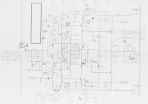
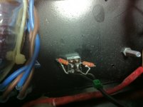
Hi Bonsai,is this what you speak about?
Attachments
I have also A1381 and C3503 from Mouser, but they are not the same grade (E and D), that's why I did not use them. I could try to change for them, but only if there is a good reason to do so...
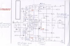
Could something have been damaged during the very first trial with R6 adjusted to minimum, when all the fuses have blown up (1A fuse in the negative, the DVM 10A fuse in the positive rail)?
Could something have been damaged during the very first trial with R6 adjusted to minimum, when all the fuses have blown up (1A fuse in the negative, the DVM 10A fuse in the positive rail)?
Last edited:
I have just made trials with various R20 values (with R6 maximum and 26V supply voltage) :
2.2k : blows fuses
3.2k : 1.8A
4.2k : 1.53A
5.2k : 1.3A
6.2k : 1.27A
So my problem might be considered solved with 5.2k or 6.2k (it looks as if there is not much point going higher with R20, as there is not much diffference with these 2 values)
2.2k : blows fuses
3.2k : 1.8A
4.2k : 1.53A
5.2k : 1.3A
6.2k : 1.27A
So my problem might be considered solved with 5.2k or 6.2k (it looks as if there is not much point going higher with R20, as there is not much diffference with these 2 values)
@ hahfran
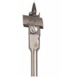
I used this type of adjustable wood bit, removing the graduated part and wedging the copper wire under the screwed one. Then turning the bit with a battery drill, forcing the wire on the bit with my fingers... all four coils as nice as this one in a few minutes.
I used this type of adjustable wood bit, removing the graduated part and wedging the copper wire under the screwed one. Then turning the bit with a battery drill, forcing the wire on the bit with my fingers... all four coils as nice as this one in a few minutes.
Attachments
@ hahfran
I used this type of adjustable wood bit, removing the graduated part and wedging the copper wire under the screwed one. Then turning the bit with a battery drill, forcing the wire on the bit with my fingers... all four coils as nice as this one in a few minutes.
great idea but how to control or determine the coil diameter ? You know for theorists winding coils is a nightmare.... the quality factor of a coil is determined by diameter as well as by distance of the winding to winding...in some cases a printed coil is better but not for high current
great idea but how to control or determine the coil diameter ? You know for theorists winding coils is a nightmare.... the quality factor of a coil is determined by diameter as well as by distance of the winding to winding...in some cases a printed coil is better but not for high current
If you have some trepidation of winding your own coils - fear not - as there are professional winders who will do small quantities:
I Wind Coils | Custom air core inductors
Best,
Anand.
Hi Bonsai,is this what you speak about?
Yes.
I am surprised at your very high readings Sadhill.
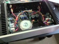
I am looking at the VAS transistor in the top left hand side of your picture - is it the right way up because I can see no logo on it - is it not upside down?
Please check and make sure R6 and R21 are also the correct values. Also, if the bias control transistor was faulty (e.g. fake) you would have issues. I am going to open my sx-amp now and check it.
Last edited:
I am definitely using 2.2k for R20 - the resistors are on the 'Hi/Lo' bias setting switch which is mounted on the bottom plate of the amp.
On the PCB, I have 12k where the 2.2k used to be - so the total actual resistance for R20 when the switch is closed is a bit over 2k Ohms.
You definitely have a problem Sadhill - with 2.2k you should not blow any fuses
On the PCB, I have 12k where the 2.2k used to be - so the total actual resistance for R20 when the switch is closed is a bit over 2k Ohms.
You definitely have a problem Sadhill - with 2.2k you should not blow any fuses
Attachments
Last edited:

- Home
- Amplifiers
- Solid State
- SX-Amp and NX-Amp