Let me explain: in the write-up that if you connect the Zobel to the amplifier ground wire - which is about 15-20 cm long in a typical wire-up of this particular design, you could be injecting HF Zobel currents into the ground wire. You could locate the Zobel at the speaker terminals, but that means messy wiring. If you look at the wiring, the amplifier output goes out to thespeaker, back via the return and then to the PSU 0V. Where possible of course, the output + and return are twisted together to reduce loop area.
On the sx and nx Amplifiers, the Zobel wire runs from the amp output, in parallel with the main ground wire directly to the PSU 0V. No HF currents are injected into the amplifier module ground. I nestimated the typical ground wire inductance to be in the order of 0.2 to 0.4 uH at 15nH per cm. Both of these designs will happily swing full rail into 8 Ohms at 100 kHz square or sine wave and not break into a sweat. The Zobel however does not like it and smokes readily (when doing this test, disconnect the Zobel).
Of course, if you put everything on one board, you can use a star ground, so this problem is resolved, albeit in a different manner. However, the comments about the smoking Zobel still apply.
Note, a number have builders have commented on how quiet these amps (sx and nx) are - one of them used to drive a pair of 96 dbW horns.
Bonsai,
Fantastic job on the design documentation of Ovation SX design (15-25 watts Class A). My speakers are 96 dB efficient (min. of 4.9 ohms and a low capacitative phase angle), so I am particularly interested.
I understand that you have implemented the zobel network on the supply board. However, I do have my own supply boards, and can easily PTP the zobel onto my supply board as detailed in your design doc. My question is, are the main boards available separately?
Thank you,
Anand.
Thanks for your comments Anand - appreciated.
Unfortunately, the boards are no available separately - Jim's Audio sells them as a kit. I think at $25 for a set plus c. $6.25 for shipping its still a bargain if you don't use the PSU board (you could always use it for a future project!). The boards are fully THP, solder mask, silk screen and gold flashed - very high quality.
For the Zobel, I'd just wire it from the amplifier output directly to your 0V on the PSU where the two filter caps connect.
Thanks for taking the time to write up that explanation.
I still don't agree.
The Zobel has been discussed and explained by me in many posts, maybe dozens by now.
I gave you the opportunity to discuss your particular implementations. After a couple of months you came back and said yes, you were willing to discuss, but then totally ignored my PMs and posts.
Some year or so later you eventually accepted the relocation of HBRR which I had described in many posts. It's like using a toffee hammer to drive in a 6" nail. You are hard work.
Last edited:
The protection+PSU PCB is a great resource. Some component values need sorting (that was another area I wanted to discuss with Bonsai), but the added protection circuitry is in my mind almost mandatory if you want to protect speakers.Thanks for your comments Anand - appreciated.
Unfortunately, the boards are no available separately - Jim's Audio sells them as a kit. I think at $25 for a set plus c. $6.25 for shipping its still a bargain if you don't use the PSU board (you could always use it for a future project!). The boards are fully THP, solder mask, silk screen and gold flashed - very high quality.
For the Zobel, I'd just wire it from the amplifier output directly to your 0V on the PSU where the two filter caps connect.
The Zobel has been discussed and explained by me in many posts, maybe dozens by now.
This isn't very helpful to anyone. There are millions of posts on this site. How is anyone supposed to be able to find something you mentioned somewhere, without any direction as to where to look?
Yes that would have helped in this situation. I suspect Bonsai has a very busy schedule, so things like this get put off and forgotten about.
I have seen your reply in quite a few threads that you had already discussed something elsewhere, but with no direction or clue where. You do post a lot of good information, and others come across posts saying something along those lines. It would be beneficial to all to have some idea where to look.
I have seen your reply in quite a few threads that you had already discussed something elsewhere, but with no direction or clue where. You do post a lot of good information, and others come across posts saying something along those lines. It would be beneficial to all to have some idea where to look.
AndrewT, I have explained my rationale for the Zobel. If you have a better way of handling it, feel free to put it up and lets discuss it.
I think the HBRL and HBRR issues have been resolved and I said as much - there was a discrepancy between the circuit and the board - the board is correct the circuit was not.
You do seem to have a habit of jumping in with both feet and or critiquing other peoples designs. No problem in that, but you also need to accept there is more than one way to solve a problem.
Do you know how a Zobel works and what its for?
Yes and the search is not that helpful because I post so often.
Just did a search on my name and "Zobel".
It came back with 566 posts.
My point exactly.
Didn't mean to start a "Zobel layout, configuration and implementation war" but it sounds like that was in place long before I posted here. I will let the intelligent cognoscenti duke it out ")
The SX version of the PS has no speaker protection that I see only the NX version just to clarify.
Very well, the best thing to do is to buy the board set and sell the PS board should somebody want a dual mono ps setup.
Thank you Bonsai for your contribution to the DIY denizens across the pond. You have furthered our understanding of CFA topology while expanding upon the earlier works of Pass, JLH and Hiraga.
Thank you Andrew for educating the uneducated, uninformed DIY neophytes.
Best,
Anand.
You do seem to have a habit of jumping in with both feet and or critiquing other peoples designs.
It seem, many people feel the same.
Even someone PM me wrote about it.
Amplifier Output Zobel and supply rail decoupling.
Why should I dip one foot in?
I might as well go full body, if it's something I believe in.
The Amplifier Output Zobel can only operate at frequencies well above the audio passband.
In fact well above 20kHz and typically it works for frequencies exceeding 100kHz. (the standard 10r+100nF Zobel has an F-3db of 159kHz). The Zobel becomes the dominant load at greater than 200kHz. Look at a typical loudspeaker impedance curve. It shows rising impedance at 20kHz. Where would it be at 100kHz and 200kHz?
At these very high frequencies the capacitive reactance in the typical Zobel is small enough that the resistor portion becomes the dominant load.
The amplifier sees this resistor load at those very high frequencies.
This does two things for the amplifier.
The resistor provides a "load" if the speaker has been disconnected.
The resistor in providing that very high frequency load allows the amplifier's "normal" gain to operate. Without that load the amp gain can, in some designs, increase to the point that the stability margins change and can even become inadequate to prevent oscillation.
All of the above REQUIRES that the Zobel resistor becomes the dominant load at very high frequencies.
If there is some inductive reactance in the Zobel route, then the inductance may share some of the load with the resistor. This could become sufficient to destabilise the amplifier.
In my reviewing of the literature, it seems that at very high frequencies the remote PSU no longer supplies much of the current going into transients generated by the amplifier.
The MF (DeMF) and HF (DeHF) decoupling capacitor take a big proportion of the high frequency currents. At very high frequencies the deHF eventually become the dominant supplier of amplifier transient current. These MF and HF decoupling capacitors can only do their job of supplying high frequency currents if their loop impedance is VERY LOW.
This is acheived by putting the DeHF at the output transistor lead outs. R.Cordell states that there is a case for adding HF decoupling to EACH output transistor to obtain that low loop impedance. Few others seem to mention this, but many do state the importance of low loop impedance even if they use different words to describe the requirement.
Note that the decoupling capacitors are not there to supply speaker current. That would be low frequency current. That low frequency current can come from the remote PSU. At frequencies of 20kHz and below the loop impedance of the PSU wiring can be tolerated.
At the higher frequencies, the PSU is basically there to recharge the decoupling capacitors so that at the next transient they have been sufficiently replenished to supply the next transient current.
Let's look a bit more closely at the output devices supplying transient current into a load. The output device uses the DeHF as it's source of current to supply HF transients to a load.
We know that the HF decoupling can only supply very short period current transients. They don't store enough charge for longer duration transients. The longer duration transients are fed from the DeMF
Their ability to achieve this is set by the low loop impedanace around a route for those very high frequency currents.
Where does that current route go and what components & traces does it pass through?
Taking an EF output and considering only the upper +ve half wave transient (particularly the sudden current change from zero current to a steeply rising current at the start, or end, of a halfwave transient) :
The current flows from device emitter, trace, emitter resistor, trace, R of Zobel, trace, C of Zobel, trace (this trace is the HF power ground), HF deCap, trace , device collector to return through the output device.
That complete route MUST be LOW loop impedance. All the traces must be short and preferably enclose a low LOOP AREA.
Slower transients can and will use the MF decoupling capacitors. One can look at the route followed by the slower transients and see that they will follow a slightly longer route because we choose to locate the MF decoupling a bit further from the output device/s.
Even these slower transients are still way above the audio frequency band. Remember that typical F-3db of the Zobel is around 160kHz. Any route that passes through the Zobel must of necessity pass a very high frequency transient. The capacitor in the Zobel ensures that slower transient are impeded by the capacitive reactance.
The whole reason for adding DeHF and DeMF to the amplifier supply rails is to supply very high frequncy transients. When they are allowed to do this job properly, they significantly attenuate the HF supply rail modulation.
Low frequency currents pass into the loudspeaker, instead of into the Zobel. These LF currents are able to take the low frequency route because they are not impeded by the long cables and inductances we place in that audio frequency route. We put speakers at the ends of longer routes because we know that works. The LF current cannot pass through the Zobel, because the impedance is too high to pass any significant current.
That's why the Zobel does not overheat when we ask the amplifier to process a maximum level 20kHz signal. Change that to a 20kHz squarewave with fast rise/fall times and the extra HF content at 60kHz and above will pass significant current through the Zobel. The resistor and the esr inside the capacitor both absorb energy.
What if we move the amplifier's output Zobel to a remote location, rather than at the output devices?
The inductive impedance rises. The DeHF probably contributes near nothing (0.1%) because the MF decoupling capacitor which is typically one thousand times more capacitance may just about be able to send some of the transient current along the longer route and back to the output devices. The output devices are the Source and any current coming out of that source must return to that source.
The remote PSU is the source for audio frequency signals and currents. This will augment the DeMF in supplying transients when the longer remote Zobel route is imposed on the amplifier.
Locating the output Zobel beside the remote PSU forces the HF transients and the audio frequencies to follow the same long route. Any advantage that the MF decoupling could have obtained from it's short on board traces is thrown away. The HF decoupling has become virtually useless.
Compare a simulation of the effect supply rail decoupling has on the performance of a realistic amplifier where route impedances have some real inductance added into the idealised ZERO IMPEDANCE traces that all normal simulation imposes.
Considering for a moment a real amplifier, I recently reported the effect that Leach found when he omitted the MF decoupling from his amplifier and relied on only the HF decoupling. It oscillated. Yet it was a stable amplifier.
He reports in his paper that the oscillation was cured by putting in the MF decoupling.
Similar anecdotes can be found where HF decoupling has been omitted.
An amplifier relies on good supply rail decoupling for excellent performance. This MF/HF decoupling is there to supply transient currents of very high frequency (short duration) that the long route from a remote PSU cannot supply. And all the HF portions have to pass through the output Zobel.
Last edited:
Andrew,
That's a very good explanation about decoupling and the flow of currents around and from the amplifier output. But the question was, given your criticism of the sx and nx amplifier Zobel designs and location how would you do it?
If you have a genuinely good insight, please share the specifics.
That's a very good explanation about decoupling and the flow of currents around and from the amplifier output. But the question was, given your criticism of the sx and nx amplifier Zobel designs and location how would you do it?
If you have a genuinely good insight, please share the specifics.
The Zobel passes very high frequencies.
The HF decoupling supplies the current for those very high frequencies.
The Zobel current should be returned to it's source
The speaker passes audio frequencies.
The PSU supplies the current for the audio frequencies.
The speaker current should be returned to it's source.
The HF decoupling supplies the current for those very high frequencies.
The Zobel current should be returned to it's source
The speaker passes audio frequencies.
The PSU supplies the current for the audio frequencies.
The speaker current should be returned to it's source.
The loop with the Zobel returning back to the 0V is small - the wires are bunched together. Local decoupling on the board is good, but caps are not perfect as you well know. If you return the Zobel to the on board 0V in a practical case (= real world caps) you will still have issues. The trade off is loop area vs common impedance coupling. I chose the latter as the greater evil to avoid.
Hi Bonsai and everyone.
I've just received a Quad 405 clone chassis from my friend and find it just perfect for a project like the NX.
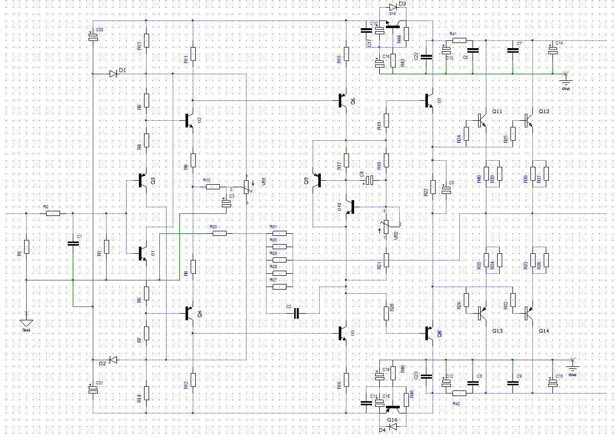
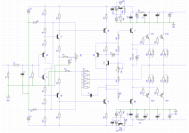
I'm trying to make my own PCB to fit the specialized chassis.Please tell me if there is any error on this schematic ? I've followed the schematic in Bonsai's PDF closely but who knows if i did something wrong
PDF and picture attached below.
Many thanks.
I've just received a Quad 405 clone chassis from my friend and find it just perfect for a project like the NX.
I'm trying to make my own PCB to fit the specialized chassis.Please tell me if there is any error on this schematic ? I've followed the schematic in Bonsai's PDF closely but who knows if i did something wrong
PDF and picture attached below.
Many thanks.
Attachments
- Home
- Amplifiers
- Solid State
- SX-Amp and NX-Amp