Hi,
To me it looks like a common mode choke. We do not want high AC impedance (differential). Se this document: http://www.murata.com/products/emc/knowhow/pdf/26to30.pdf
To me it looks like a common mode choke. We do not want high AC impedance (differential). Se this document: http://www.murata.com/products/emc/knowhow/pdf/26to30.pdf
See, now you understand why I am unsure on this. It seems everyone else is too!
I thought it was strange though that common-mode noise on the L/N lines would be filtered and yet ground would be unfiltered. I have a friend who once asked me if there was a way to isolate line ground from the amp and chassis without causing safety issues. I suggested ultrafast, low-capacitance diode strings, which would fail shorted, hopefully. Or very low-voltage spark gaps like those used in ancient modems. Or just a large choke, paralleled with diode strings to absorb kickback from sudden ground currents. We agreed that such a system would have to be at least as safe as a direct ground connection.
I thought it was strange though that common-mode noise on the L/N lines would be filtered and yet ground would be unfiltered. I have a friend who once asked me if there was a way to isolate line ground from the amp and chassis without causing safety issues. I suggested ultrafast, low-capacitance diode strings, which would fail shorted, hopefully. Or very low-voltage spark gaps like those used in ancient modems. Or just a large choke, paralleled with diode strings to absorb kickback from sudden ground currents. We agreed that such a system would have to be at least as safe as a direct ground connection.
")
The common mode is followed by a cap to ground.
Any impedance on the line before the cap will create a filter and that filter will attenuate the signals. Yes there is some differential mode attenuation. The paper in post 944 starts by showing the equivalent circuits for the common and differential mode filters, from the same common mode inductor without changing any of the 4 PIN connections.
Those are equivalent circuits.
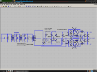
Here is my PSU so far. The 1.5u+7R RC at the rectifier was arrived at though real-life testing. For suppresion of the 500KHz resonance, a 220u+47R network could be added, but the cap and resistor might promptly explode, too bad. However, even partial suppression of the 500KHz resonance may prove more important, so I may end up increasing the 7R resistor.
No visible ringing on either scopes. The linear filter is a pretty beefy Feller AG, but one of those files posted earlier shows a nice line filter that I should perhaps emulate.
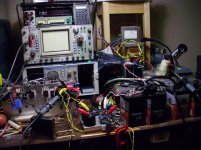
What do you guys think? This is my bench supply, the Fetzilla isn't what's on right now, but, you know, hypothetically... Those convolutions near the end are my high-current Kmultipliers.
Yes, that is a Tektronix FG504 signal generator... A very generous friend helped me acquire it.
No visible ringing on either scopes. The linear filter is a pretty beefy Feller AG, but one of those files posted earlier shows a nice line filter that I should perhaps emulate.
What do you guys think? This is my bench supply, the Fetzilla isn't what's on right now, but, you know, hypothetically... Those convolutions near the end are my high-current Kmultipliers.
Yes, that is a Tektronix FG504 signal generator... A very generous friend helped me acquire it.
Attachments
If R9 is too low, the 500KHz resonance turns into a 5KHz resonance! I found a good middle value was 25R. Turns out a huge cap is not needed for 500KHz suppression, it was a testing mistake. If I increased C19 to 4.7u, maybe I could score both birds, but that would be a big cap...
I found that I needed a C & R across each secondary to keep the earth clean.
I have successfully used 4.7uF + R but I always used 0.1uF as well.
the 0.1uF reduces the the frequency and provides some added filtration. ( Reducing the frequency is good - most regulators and caps etc work well in the 1k - 5k band, 500khz is more challenging )
the C + R damp this lower resonance.
your ears should confirm this mod
Last edited:
The 100nF cap may not reduce the winding resonant frequency, it may just give the windings and open circuit to resonate into. I would put a small resistor in series, 1-10R. This could be a trimmer, as there are resonances above 1MHz that could be rather conveniently damped here. I do have a 10nF there though, maybe I will mess with it.
Many people like to have as little ESR as possible, but I keep finding myself wanting to add series R to keep the caps from resonating with each other and various things.
Many people like to have as little ESR as possible, but I keep finding myself wanting to add series R to keep the caps from resonating with each other and various things.
- Status
- This old topic is closed. If you want to reopen this topic, contact a moderator using the "Report Post" button.
- Home
- More Vendors...
- AKSA
- Swordfishy/ASPEN FETZILLA power amp