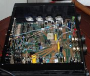
OK So I finally got around to putting a direct input on the back of my Integrated Series 200 Playmaster amp. Initially this is so I can run my HT PC direct into the amp bypassing the preamp section, but still have the rest of the preamp switching available for other inputs.
Basically I stuck a DPDT switch in between the 1K output resistors of the preamp and the 1uf input caps on the power amp. The switch is a simple toggle switch, center on off on.
Switching to the off position presents no problem at all. However switching to either preamp, or direct input results in a large thump from the speakers. The amp has relays on the speaker output and I could put a three pole double throw switch in and simply switch the relays off when switching inputs, which would probably do the trick, but I was wondering if there was anything else I could do.
I'm a little concerned that when I make a new preamp (as the excercise has definitely highligted there are deficiencies in the built in one which I had long suspected) that depending on the design I may still have a problem. The amp is eventually going to become my sub amp, and would be connected to a pre with an active crossover, and probably a B1 buffer on the outputs. I suspect I won't have a problem, but since I don't know exactly what causes the thump I'd like to know what the usual cause is and what workarounds if any there are.
The existing preamp does have switching noise but it is limited to a very soft high freq click. The switching mechanism in the pre (and probably the main cause of problems) is all electronic using cmos analog switches and ne5534 buffers.
So to cut a long story short, if anyone can give a likely explanation of what is causing the thump, and possible solutions, that would be greatly appreciated")
Tony.
Basically I stuck a DPDT switch in between the 1K output resistors of the preamp and the 1uf input caps on the power amp. The switch is a simple toggle switch, center on off on.
Switching to the off position presents no problem at all. However switching to either preamp, or direct input results in a large thump from the speakers. The amp has relays on the speaker output and I could put a three pole double throw switch in and simply switch the relays off when switching inputs, which would probably do the trick, but I was wondering if there was anything else I could do.
I'm a little concerned that when I make a new preamp (as the excercise has definitely highligted there are deficiencies in the built in one which I had long suspected) that depending on the design I may still have a problem. The amp is eventually going to become my sub amp, and would be connected to a pre with an active crossover, and probably a B1 buffer on the outputs. I suspect I won't have a problem, but since I don't know exactly what causes the thump I'd like to know what the usual cause is and what workarounds if any there are.
The existing preamp does have switching noise but it is limited to a very soft high freq click. The switching mechanism in the pre (and probably the main cause of problems) is all electronic using cmos analog switches and ne5534 buffers.
So to cut a long story short, if anyone can give a likely explanation of what is causing the thump, and possible solutions, that would be greatly appreciated
Tony.
Attachments
Tony, I am not at all familiar with your amplifier, but make the general observation that most switching thumps are caused by the presence of DC on the sources you are switching to. It could also be caused by an input capacitor having no input terminating resistor to bleed away any charge it may have acquired. This seems unlikely as any half decent amplifier would have taken care of this.
Have a look at the output circuitry of your sources. If there is no coupling capacitor (unlikely) you may have to add one. If there is one make certain that there is a high value bleeder resistor from output to ground.
Keith
Have a look at the output circuitry of your sources. If there is no coupling capacitor (unlikely) you may have to add one. If there is one make certain that there is a high value bleeder resistor from output to ground.
Keith
Basically I stuck a DPDT switch in between the 1K output resistors of the preamp and the 1uf input caps on the power amp
It could also be caused by an input capacitor having no input terminating resistor to bleed away any charge it may have acquired.
I think Keith is right on it.
Try put in a 100K resistor from the input side of the power amps cap to ground
Thanks Guys I'll give it a try, yes certainly with what I have done there is no Bleeder resistor for the direct switched input. There are on the other inputs but this is at the input of the preamp section so I guess that I'm seeing an "accumulation" of dc on the output of the pre while it is switched off. Will be simple to add a couple of resistors, and if it fixes the problem much better than wiring into the speaker relays. Should be able to do this some time today. I'll report on the results
Tony.
Tony.
OK well I didn't have any 100K resistors on hand, so used the closest I had which were 68K. Completely fixed the thump for the direct input but made it worse for the preamp input It now thumps both swithching on and off.
I decided to try moving the resistors to the rca jacks on the direct input so at least I'd have one switch movement without problems but this didn't have the desired effect either. happily can switch the direct input on and off without a thump. thumps as expected when going back to preamp, but then thumps again when going to direct...
Decided to check the output of the preamp. It has -1.1V on it!!! No wonder I'm getting a thump!! There used to be a 22uF bipolar where I am taking the feed from, it used to feed into another opamp for the tone controls, followed by yet another for the balance pot... I think I need to investigate why that stage has such a large DC component, or consider putting in a cap between the preamp and the switch...
I'll check the circuit for the preamp and see if there is anything I can do to reduce the DC offset. as that I think would be prefferable to sticking another DC blocking cap in...
Thanks guys
Tony.
It now thumps both swithching on and off. I decided to try moving the resistors to the rca jacks on the direct input so at least I'd have one switch movement without problems but this didn't have the desired effect either. happily can switch the direct input on and off without a thump. thumps as expected when going back to preamp, but then thumps again when going to direct...
Decided to check the output of the preamp. It has -1.1V on it!!! No wonder I'm getting a thump!! There used to be a 22uF bipolar where I am taking the feed from, it used to feed into another opamp for the tone controls, followed by yet another for the balance pot... I think I need to investigate why that stage has such a large DC component, or consider putting in a cap between the preamp and the switch...
I'll check the circuit for the preamp and see if there is anything I can do to reduce the DC offset. as that I think would be prefferable to sticking another DC blocking cap in...
Thanks guys
Tony.
OK well it looks like it isn't as simple as what I might have hoped. The original circuit designers just accepted the offset and stuck in the 22 uF bipolar to get around the problem. I was thinking that maybe I could stick a 47uf cap between the feedback resistor and ground to reduce the offset maybe down to around 170mV (the gain is set at 5.6, so I'm assuming this would work). Still not great but a lot better that 1+ V
It seems the solution is to put a pot in and inject an equal voltage on the input (which doesn't have an offset) which should cancel out the output dc offset. Since my offset is negative I assume I would need to apply this on the positive input.
It's starting to sound like it will be easier to get off my backside and build my new preamp!!
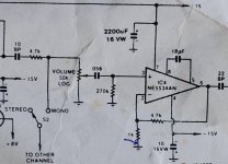
circuit diagram is attached. I'm taking the feed for the amp at the point where the 22uF bipolar electro is. Interestingly I put in a 1K resistor there, I can't remember why, so I have the output of the opamp, 1K resistor, switch, 1uF input cap of the amp. I'm also thinking that 1uF polyester cap is really not going to be blocking the 1.1V -ve dc offset very well!!! The arrow is where I was thinking I could shove in an electro to at least drop the gain to unity at DC.
Tony.
It seems the solution is to put a pot in and inject an equal voltage on the input (which doesn't have an offset) which should cancel out the output dc offset. Since my offset is negative I assume I would need to apply this on the positive input.
It's starting to sound like it will be easier to get off my backside and build my new preamp!!
circuit diagram is attached. I'm taking the feed for the amp at the point where the 22uF bipolar electro is. Interestingly I put in a 1K resistor there, I can't remember why, so I have the output of the opamp, 1K resistor, switch, 1uF input cap of the amp. I'm also thinking that 1uF polyester cap is really not going to be blocking the 1.1V -ve dc offset very well!!! The arrow is where I was thinking I could shove in an electro to at least drop the gain to unity at DC.
Tony.
Attachments
Hi,
your output offset = [270k-1k] * input offset current * [4k7/1k0 + 1]
You can reduce the output offset by reducing any or all of the three terms.
Reduce the resistance difference seen by the +in & -in pins. 270k becomes 50k
Reduce the input offset current. FET input opamp.
Reduce the DC gain. Configure as opamp follower or AC coupled.
BTW,
that 0u056F coupling cap kills the bass response. RC~15ms.
Try 0u47F to get RC~120ms. If you go for 50k, the pot should be reduced ~10k and the coupling cap ~2u2F
Why is the comp cap fitted to the 5 & 8 pins?
Was this a follower stage that needed the comp cap for low gain stage?
Who changed the circuit?
Last edited:
Putting a capacitor where you suggest to reduce the DC gain to unity seems a good idea. The reason you would have put a 1K in series with the output is to reduce the phase shift that cable capacitance may introduce at the feedback pick off point were it not there. This can lead to instability. Presumably you have ceramic bypass capacitors near the 5534 supply pins in addition to the electrolytic caps?.
If you have an oscilloscope it may be worth looking at the output, as sometimes what appears to be a DC offset may be very high frequency oscillation with an assymetrically clipped waveform.
Keith
If you have an oscilloscope it may be worth looking at the output, as sometimes what appears to be a DC offset may be very high frequency oscillation with an assymetrically clipped waveform.
Keith
How about dumping the 5534 buffers and fitting any of the discrete buffers that abound on the Forum?
Start with the VERY SIMPLE, but effective, B1 by PASS.
Thanks AndrewT that IS the plan I read about the B1 recently and decided that was what I wanted
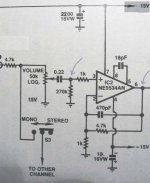
this mod was the first stage to bypassing the sunstandard pre, just didn't expect the switching problems. I've got a feeling I have increased those .056uf caps in a previous mod of the circuit. (actually I'm pretty sure that they are .22uf Now) see attached schematic this is what I changed to there are a couple of other differences as well. The volume pot is a 50K linear with a (seems a bit low) 1K lawfaking resistor. There are a number of stages in the circuit that use the 5534's (after this one) which are unity gain, so would have required a comp cap to stop oscillation. even with those the circuit was prone to oscilation and there have been a couple of other mods I did to it to fix that (based on a later published design the playmaster 60/60 which used an almost identical preamp section. I suspect that they just put it in to be consistent. I did experiment with different comp caps before I found a post where I said I considered removing them completely as the datasheet says they aren't needed with gains of 3 or higher.. Revisisting that thread brought back some memories, had a nightmare of a time with weird preamp - amp interactions... The 1K resistors between the opamp and the 1uf input cap were suggested by Clem_o, I knew there would be a reason that they had been put in.
I'm actually thinking I will just go out and get some 22uf bipolars and stick them in as a work around until I make my B1. I took the grills of the speaker today and the deflection in the woofers is severe, I'm sure it is not doing them any good at all! Better to be safe than sorry I think!
The only thing I'm not sure about is whether I should just stick the 22uF bipolar in series with the 1uf polyester, or whether I should have any resistance in between, perhaps leave the 1K and also put in the 100K to earth.
The really ironic thing is that I said in that thread back in 2005 that I should just get on with making a separate pre... as I said it sometimes takes a while for my visions to come to fruition
Tony.
Attachments
Putting a capacitor where you suggest to reduce the DC gain to unity seems a good idea. The reason you would have put a 1K in series with the output is to reduce the phase shift that cable capacitance may introduce at the feedback pick off point were it not there. This can lead to instability. Presumably you have ceramic bypass capacitors near the 5534 supply pins in addition to the electrolytic caps?.
If you have an oscilloscope it may be worth looking at the output, as sometimes what appears to be a DC offset may be very high frequency oscillation with an assymetrically clipped waveform.
Keith
Keith spot on with the 1K resistor I went searching my old threads, and it was at the suggestion of clem_o for the exact reason you have stated (well at least the stability part). I did add in bypass caps at one point but may have removed them again I'm not sure... was at a time the thing was giving me hell, and after I got it working I just didn't touch it (one of the posts mentioned taking them out in case they were causing my problems). I still haven't got myself a scope, but I have always suspected there is a certain amount of oscilation happening! I went looking for one again recently, but they are expensive here in Aus... often going for extremely high prices secondhand
apparently you can occaisionally get a bargain on ebay but I haven't succeeded yet. Tony.
OK Well tonight I searched through the parts box stashed in the cupboard, and found a bunch of goodies left over from my Gainclone build. Discovered I'd bought enough rectifier diodes to make a couple of discrete bridges (which I've been planning for ages, and some 47uF Nichicon FG's.
I put the 47Uf into the negative feedback circuit between the 1K resistor and ground. measured the voltage first and found it was negative on the resistor so made sure I mounted the elctros properly
It certainly had the desired effect, DC on the output dropped from ~1100mv to 210mv on one channel and from ~1200mv to 230mv on the other.
Switching thump is still there but it is much more subdued. Decided to try this first as it was the simplist mod (short of putting a bipolar electro in) that I could do, and it certainly has reduced the risk of damage to the speakers substantially.
Whether I will continue the quest to remove the thump, or just get on with my speakers and preamp waits to be seen
Tony.
Yep that was the easy win (which is why I tried it first Was pleased to see that my plan worked (must have learn't something over the years..... though it showed that my mental arithmetic was a bit off ).
The tweaker in me wants to play till it has a little offset as possible. The realist in me says leave it alone as the tracks on the pcb look like they will peel off any second! To many mods, and use of dodgy soldering irons years ago before I got a decent soldering station has rendered the pcb in a very bad way. The other thing is I really really don't want to touch the volume pot! It is working well (probably the only one in the amps 20+ year history) and I'd really rather leave well enough alone
Oh BTW I confirmed that the 0.056 caps have been replaced with .22uf and the comp caps on the ne5534 have been reduced to 4.7pf by the look of the resistors soldered onto the reverse side of the circuit board the exta 1k resistors (and possibly some others) have also been added.
cheers,
Tony.
Was pleased to see that my plan worked (must have learn't something over the years..... though it showed that my mental arithmetic was a bit off ). The tweaker in me wants to play till it has a little offset as possible. The realist in me says leave it alone as the tracks on the pcb look like they will peel off any second! To many mods, and use of dodgy soldering irons years ago before I got a decent soldering station has rendered the pcb in a very bad way. The other thing is I really really don't want to touch the volume pot! It is working well (probably the only one in the amps 20+ year history) and I'd really rather leave well enough alone
Oh BTW I confirmed that the 0.056 caps have been replaced with .22uf and the comp caps on the ne5534 have been reduced to 4.7pf by the look of the resistors soldered onto the reverse side of the circuit board the exta 1k resistors (and possibly some others) have also been added.
cheers,
Tony.
- Status
- This old topic is closed. If you want to reopen this topic, contact a moderator using the "Report Post" button.
- Home
- Amplifiers
- Solid State
- switching thump...