Hi
That should be fun.I have mod my to give me 13.5v, but it can easly be done for other voltages. What you need to do is to remember primary turns, and sec, wind it x that you have on, to get to 50. If there are 3 to get 5v I would try to put 30, but you should do some calculations, because probably you will need less than just multiplied x10.
Here great site to calculate for unregulated, you just add let say 20% more just to be sure.
Hi,
I have been trying to put others off the idea of SMPS for ClassAB amps. Part due to interaction between supply and active load and part to do with safety for the user/builder.
Can you guys show how it can be done safely?
I just opened up my mother's TV to find the supply was a direct online rectifier feeding a 400Vdc capacitor that must have been running at near maximum voltage to feed the SMPS.
No earth in sight and just a fuse blown. All working again.
Simple, light weight, cheap, all in no doubt. Help convert the biased.
I have never considered a computer supply as a take off point, but I do think that a switching power supply for a linear amplifier is a good idea. It seems to me that this might be harder than it sounds because a computer supply is designed for high current at much lower voltages. The other catch is that it may be difficult to duplicate from one supply to the next.
With a conventional 50/60 Hz unregulated supply, you can only replenish the rails at a 100/120Hz rate. The power supply caps are never really big enough.
If the switcher operates above the audio frequency range, the supply will never sag very much. You still need to have good power supply rejection in the VAS stage. This will be a little more difficult since the power supply noise will be at a higher frequency, but I think the amplifier will probably perform better.
I've built lots of switching supplies but nothing higher power. I think this might be an interesting area to explore further.
From a safety point of view, I don't think this is much different than any other type of supply. Don't touch the rail voltages......
Perhaps this topic has discussed at length in the Class D section.
Al Clark
Gold_xyz said:I would like to modify an old PC's supply for +/- 50V
or build a new PSU switching for my amplifier.
(today a cheap PC supply can deliver over 500W)
I look for to realize a light and compact amplifier but without abdicating the quality of class AB...
some suggestion?
I know my way around a soldering iron, yet the books I picked up on switching power supply design convinced me I didn't want to play around with something which could fry me stone dead in a second. There's a reason SMPS consultants get $150/hour.
On the other hand, if you really want a switcher, try these guys:
http://www.coldamp.com/opencms/opencms/coldamp/en/productos/
Gee, I've built switchers at up over 1kV, but never got $150/hour for it. Bummer. IMO, you probably want to design this from scratch, rather than fooling with a PC supply. Aside from poor docs, you'll probably have to replace every part in it. A better place to start is the switchers used in any high power automotive amp. Use the basic concept, but redo the transformer design for the right ratio for line in, and be sure the feedback system is isolated like optocouplers or such. With small loop areas and a ground plane, it should be possible to make a very usable supply. Unless you're really good (I'm not), don't expect the fantastic efficiency number you sometimes see advertised.
Conrad Hoffman said:Gee, I've built switchers at up over 1kV, but never got $150/hour for it. Bummer. IMO, you probably want to design this from scratch, rather than fooling with a PC supply. Aside from poor docs, you'll probably have to replace every part in it. A better place to start is the switchers used in any high power automotive amp. Use the basic concept, but redo the transformer design for the right ratio for line in, and be sure the feedback system is isolated like optocouplers or such.
There's also the small matter of replacing all the primary-side silicon because car power supplies are 12 volts while rectified wall voltage is about 170 Vdc.
Well, Conrad, that's not what I call a friend's advice!
Toroids used in car SMPS can be used because there is no HV involved. You won't be able to keep reasonable safety with a toroid used in an offline PSU. I wouldn't play with that, and start with a completely new ETD core instead.
All the primary side has to be changed, as DSP_geek noticed (not only the components voltage ratings, but also the topology, car SMPSs are usually push-pull, while you want a half-bridge or full-bridge for offline supply).
In a nutshell, the only part you can reuse of a car amp is the secondary side, excluding the transformer.
tease you more .....
its a very good idea also very easy to do .... this is been in my mind for very long time ..... but as everybody else long term stability is the issue ahead from performance ....
its really worth taking a look at bob carvers principal of opetration of SMPS so called track down converter....
its actually a SMPS that in real time is checking the voltage of supply to the BJT's versus the audio out put voltage
he is determing this to a safe margine of 6 volts so when audio out required is like 6 volts then power supp is something like 12 ...
resulting virtually cold running amps driving loads to almost 0.5 ohms and goes on .....
effectivity of almost 95%
in my times i ve seen some of these amps to my shop for repair meaning that often they get trouble but looking to it it seems that most of trouble begins that at the time sunfire didnt make any export versions for 230v europe use ...so all units running with normal trafos 230 to 110 and whatever comes with it ...
also sunfire products is manufactured in taiwan also whatever comes with it
digam professional amps working the same way ....you get 2.500 w from an amp sized 1 U neet eeee
Hi all !
I think not easy for this vestion !
Because am work with LINN , and Im understan how to buid switching powersuply verydiffican for Transitor ampli, its not easy because we can have hi voltage, but not hi Ampe, all power ampli transitor hiend muts be use hi Ample, not same Tube come up with ( V ),
If use PC powersuply with mod , we oly gets +- 12VDC for 3A, I m try its befor , and once day , have smocking>....finting ..oh
Veryfeell company do Switching powersuply for power amplifi .
Hi
I realy don't see what is the problem here. You can mod it to any voltage you like, even go over the max rated power.
I have mod my pc supply, that was 230w, now it has only one output at 13.5v and it does put out over 20A with no problem. Last day when I was testing somethhing, output voltage did sag a bit but it did put some over 40A for 1s or two.
luka said:Hi
I realy don't see what is the problem here. You can mod it to any voltage you like, even go over the max rated power.
I have mod my pc supply, that was 230w, now it has only one output at 13.5v and it does put out over 20A with no problem. Last day when I was testing somethhing, output voltage did sag a bit but it did put some over 40A for 1s or two.
OK Luka!
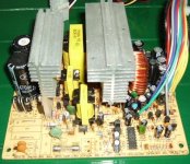
Im have some photogr about Switching powersuply .
Example: Linn Klimax Chakra , and Classik movie for you see its .

Hey, I didn't suggest modifying an existing automotive amp, just looking at the *concepts* they use. Obviously you'll have to set up the input for the required voltage. A toroid can certainly be wound and insulated for rectified mains level inputs, but I probably wouldn't use a toroid because they're hard to wind and can't be selectively gapped to get the values where you may want them to go. I believe CE regs these days require an amount of insulation between primaries and secondaries that's more easily achieved on an E-core, so agreed, that's a better choice. My only point against starting with PC supplies is the lack of documentation on most of them. If you can find a schematic, go for it.
- Status
- This old topic is closed. If you want to reopen this topic, contact a moderator using the "Report Post" button.
- Home
- Amplifiers
- Solid State
- Switching PSU for amplifiers