Tin,
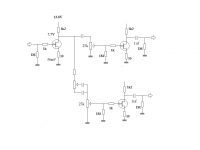
you are still showing the BJT buffer without a DC blocking cap on the input.
Without that necessary cap, anything you attach to the front end will corrupt the BJT biasing you have shown.
Look again at that 2002 pre-amp.
C1, C4, C7, C16, C17, C8, C14, C18, C19, C20 are all DC blocking caps.
you are still showing the BJT buffer without a DC blocking cap on the input.
Without that necessary cap, anything you attach to the front end will corrupt the BJT biasing you have shown.
Look again at that 2002 pre-amp.
C1, C4, C7, C16, C17, C8, C14, C18, C19, C20 are all DC blocking caps.
Last edited:
Tin,
you are still showing the BJT buffer without a DC blocking cap on the input.
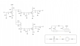
yah, I know....but right now Im working on the jfet section only
you may notice I removed output resistors
so the jfet output dc blocking cap would connect directly to the BJT buffer
but that BJT thing is just for fun
output buffer for the final preamp project will different, and have symmetric power supply
unfortunately no time for that right now
but until then I need to stay fit, and on my toes

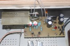
Attachments
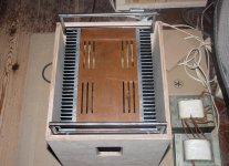
I noticed that your cabinet has quite of bit of free space...maybe are you planning to build a complete power amp in there?
you just gave me an idea
maybe it would be 'convenient' to have just a small power amp built in
to use just for 'silent practice'
it could also have optional high pass filtered output
Hi tinnitus,
Any updates for your project? Have not seen any posts for a while.
hi shanx
havent changed a thing, and its still rocking
well, one small change
I now use only one channel to drive my 3way speaker
if I continue with 2-channel preamp, the second channel will be for another instrument, like a guitar
hey....it really works
Anyways I hope you keep experimenting and have fun!
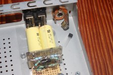
status quo of my big power amp project
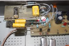
Attachments
Do you have that build going on another thread?
no, not yet
but its from apexaudio's '1000watt Simple PA Amplifier'
well, I really dont need it, but since I already got most parts, why not try it
besides, it might be fun to have such a power monster
Good luck with it.
I may need it, thanks
yeah, I suppose there will be more to post later
like said, it works fine again
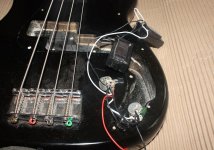
and I like the parallel pickups too
but had to change tone control cap
or else it was way too bright
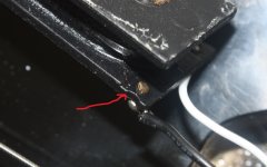
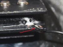
found a wire had been jammed by magnet
and I broke one coil wire
I suppose it burned from too many solderings, when testing the different configurations
not all worked well
(as a warning if you try this)
and I like the parallel pickups too
but had to change tone control cap
or else it was way too bright
found a wire had been jammed by magnet
and I broke one coil wire
I suppose it burned from too many solderings, when testing the different configurations
not all worked well
(as a warning if you try this)
Attachments
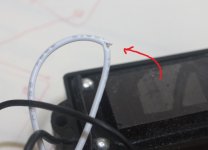
Hi Tinitus, yes those really small wires can be tricky. I avoid touching them if at all possible. If I do I rewire the other end of the cable connections with a switch. In my case it's a 5 way switch for strat style 3 pup. While you have the pickups out you may want to look at the shielding inside the cavity of the bass. Get some copper tape and line the insides, as well as the cover, and connect to your jack ground. Should be a big improvement to reducing hum and interference.
- Status
- This old topic is closed. If you want to reopen this topic, contact a moderator using the "Report Post" button.
- Home
- Live Sound
- Instruments and Amps
- Switchable Hi-Z input impedance, how ?