Hi Tinitus, in the case of your emitter follower setup , you could say that the statement ''about input Z based on bias network alone'' is precisely the reasoning for getting rid of the 2K to ground, etc. and having the DC block. With the 2 K there you are loading down the Fet for no reason, and complicating what should be a simple DC voltage divider. Right now you are trying to get a base bias by bleeding off base current (I assume through the 2K), the idea of what you need to do is increase (by a lot ) the 22 K upper resistor and leave the 60K alone more or less. Remove the 2K and the 560 'base blocker'. The 2K is swamping out any Hi Z you would normally want to have with an emitter follower. That is one reason you would want to design in a simple high resistance DC voltage divider. Those general statements come with the assumption that the stage is properly designed. In other words you can ignore the emitter side if and only if the hFE and emitter resistor are sufficiently large enough that they become negligible in calculating Zin. Don't worry it gets more fun once you start grasping it. Enough head spinning!
Cheers to you too, and just to say that I was just trying to be helpful, if I suggested something to try.. it is just to pass on some advice and that hopefully you will gain some experience and insight by trying it. Sure others posting feel the same. Everyone learns in different ways, no problem with that.. advice is free, so up to you if you choose to follow it or not. Free advice has potential great value (or not) whereas consultative engineering is sort of fixed value. Contract engineers get paid, whether you choose to follow recommendations or not. That is a whole other story though. talk soon.
Not the way they are connected.btw, aren't the 470/2k2 resistors on jfet output there to 'set the gain'.....?
I suggest studying "basic transistor gain stage" and "basic FET gain stage".
There you'll find how to calculate biasing, gain, idle current, impedance, voltage swing, etc.
All that's needed in fact.

yes, I know its never that 'simple'...but thanks anyway
btw, aren't the 470/2k2 resistors on jfet output there to 'set the gain'.....?
maybe I should replace with a series resistor
No you should just remove them, they shouldn't be there - you're probably now up to about ten unwanted (and often detrimental) resistors in the circuit.
I probably shouldn't even suggest this - but if you bias the FET's correctly you could directly couple the emitter followers to them (particularly as the bias is completely wrong on them at the moment). This would save even more resistors, and the coupling capacitors as well.
so, the jfet output resistors are only there to load the jfet output, in case it should be disconennected from the load
when mounted in the same case as load, with a fixed connection, then they are not needed
The resistor to ground 'could' be useful if it fed out externally, assuming the coupling capacitor is an electrolytic. However, it would need to be MUCH larger, it's far too small at the moment (100K would be fine) - but for the existing circuit isn't needed at all.
if you remove the resistors completely then the cap on the output of the preceding stage acts as your DC block.
You can keep the series resistor as a base stopper but a base stopper should be attached to the base, not the output of the FET.
If the two stages were connected with a removable interconnect then adding a grounding resistor to take any leakage past the DC blocker is good practice. This grounding resistor (at both ends of the interconnected equipment) can usually be >1M
Nigel,The resistor to ground 'could' be useful if it fed out externally, assuming the coupling capacitor is an electrolytic. However, it would need to be MUCH larger, it's far too small at the moment (100K would be fine) - but for the existing circuit isn't needed at all.
Tin has probably not understood my previous post, or simply ignored it.
easy guys...I only have 2 hands, and one(half) brain 
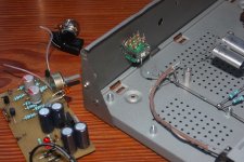
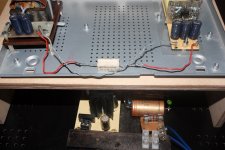
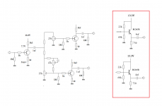
anyway...looking at this mess now
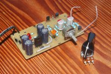
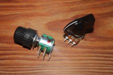
thinking about converting the onboard pot into a bass cut control, just for one channel only
from what I have seen, its only a small cap in paralel with pot
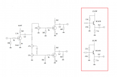
anyway...looking at this mess now
thinking about converting the onboard pot into a bass cut control, just for one channel only
from what I have seen, its only a small cap in paralel with pot
Attachments
I can't remember if I posted this for you before?, but why not build this excellent and highly regarded bass preamp?
Bass Preamp
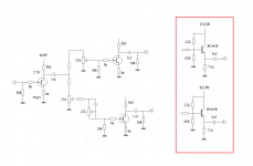
Or at least look at it's circuit, and compare it to all the incorrect components and connections in yours - here's the schematic from the site as well.
Notice in particular the value of R11 - does it's placement remind you of anything?.
Bass Preamp
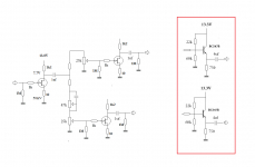
Or at least look at it's circuit, and compare it to all the incorrect components and connections in yours - here's the schematic from the site as well.
Notice in particular the value of R11 - does it's placement remind you of anything?.
Attachments
Notice in particular the value of R11 - does it's placement remind you of anything?.
sure
I suppose its there because the curcuit have a bypass switch
needs to be there not to leave the curcuit 'open', and unloaded
yeah, I know Kreuzer's site, and his work, and a some others
I suppose his preamp from 2002 is designed for acoustic bass
anyway, Im not building a preamp...yet
Im only testing my 2SK170 jfets
and those old Motorola BC547 I happen to have too
there really isnt a lot more to it than that
and Im testing how it works with plug in boards
in the end I hope to have one big mother board with power supply lines
and everything else is made of small plug in boards
thats basicly the idea
no need to rush it...the longer it takes, the more fun we have
yeah, I know Kreuzer's site, and his work, and a some others
I suppose his preamp from 2002 is designed for acoustic bass
Why would you think that?.
because they needed it
there were no preamp for acoustic bass at the time
No real difference for an acoustic preamp to an electric one (apart from higher input impedance), and there's certainly no reason to assume that preamp was for acoustic, quite the opposite.
If it was intended for acoustic bass it would have said so, yet it quite clearly refers to it as a bass preamp.


- Status
- This old topic is closed. If you want to reopen this topic, contact a moderator using the "Report Post" button.
- Home
- Live Sound
- Instruments and Amps
- Switchable Hi-Z input impedance, how ?