


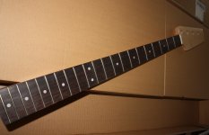
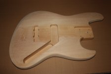
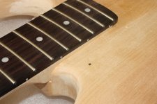
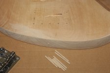
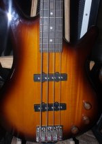
changed the shape a bit
(removing all router roundings)
and forgot to mention
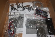
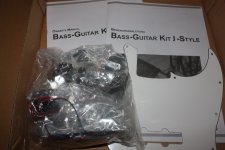
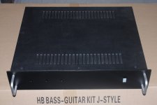
its a kit and came with all parts needed
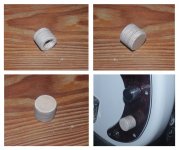
thinking about how finish/color
but not sure yet
(removing all router roundings)
and forgot to mention
its a kit and came with all parts needed
thinking about how finish/color
but not sure yet
Attachments
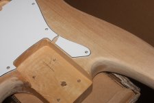
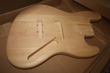
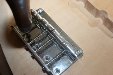
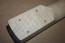
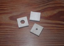
the neck joint
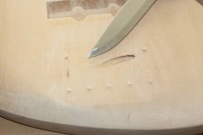
predrilled body holes are ok, and matches the mounting plate
but the holes in the neck are far off
only one hole is where it should be
I can plug the holes, and drill new ones
or consider thread inserts
fortunately the neck joint was way too tight
which means at least that is a good fit now
predrilled body holes are ok, and matches the mounting plate
but the holes in the neck are far off
only one hole is where it should be
I can plug the holes, and drill new ones
or consider thread inserts
fortunately the neck joint was way too tight
which means at least that is a good fit now
Attachments
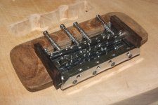
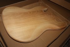
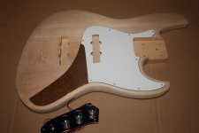
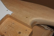
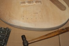
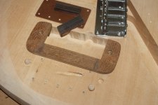
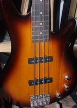
looks like the bridge moved slightly left towards E-string, and a bit forward
Attachments
Hi Tin,
Before you go any further I suggest to check alignment of bridge/neck and also the neck angle. Set it up using strings of a gauge you normally use and verify it can be adjusted to the action you want. Easier to make changes now than later. I am surprised the tailpiece holes were that far off, unless the neck pocket wasn't routed properly (the neck holes seemed to be misaligned to the body, from your picture)
Before you go any further I suggest to check alignment of bridge/neck and also the neck angle. Set it up using strings of a gauge you normally use and verify it can be adjusted to the action you want. Easier to make changes now than later. I am surprised the tailpiece holes were that far off, unless the neck pocket wasn't routed properly (the neck holes seemed to be misaligned to the body, from your picture)
Hi Tin,
Before you go any further I suggest to check alignment of bridge/neck and also the neck angle.
I did that before this, using a metal band
but small adjustments are still possible
I moved the bridge forward because I always seem to land at the end of the screws
and my 'scale'/free string length varies from close to 860 to 865(mm)
the sidewards move of bridge
Im trying place the string load so that it pulls the neck towards left side of neck joint where the body neck support is
or if you like ... avoiding the neck is being pulled towards G-string where there is no body support, and only the screw to hold it
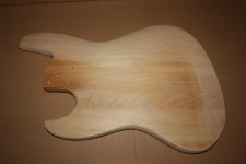
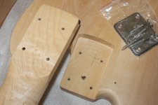
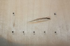
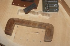
ahh, forgot to mention
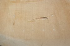
I plugged the predrilled screw holes for the bridge because the holes were too big for the screws
or else I would not have bothered
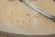
and btw, I also managed to plug the predrilled neck holes
this also gave me the opportunity to adjust the neck joint
again with focus on placing the load on the end of neck and neck joint so that the neck is not pulled sidewards
I plugged the predrilled screw holes for the bridge because the holes were too big for the screws
or else I would not have bothered
and btw, I also managed to plug the predrilled neck holes
this also gave me the opportunity to adjust the neck joint
again with focus on placing the load on the end of neck and neck joint so that the neck is not pulled sidewards
Attachments

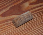
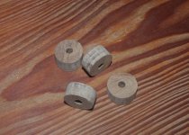
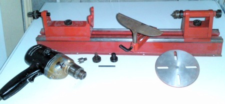
Do you have access to a wood lathe?
You can make beautiful wooden knobs there.
There's even an add-on base available, powered by a regular hand drill, which turns it into a small bench lathe.
It's not expensive and you just clamp it to your workbench (or even a kitchen table).
You can make beautiful wooden knobs there.
There's even an add-on base available, powered by a regular hand drill, which turns it into a small bench lathe.
It's not expensive and you just clamp it to your workbench (or even a kitchen table).
Do you have access to a wood lathe?
You can make beautiful wooden knobs there.
And lathes are great fun
I've not played with one for MANY years, but I really enjoyed them at school.
- Status
- This old topic is closed. If you want to reopen this topic, contact a moderator using the "Report Post" button.
- Home
- Live Sound
- Instruments and Amps
- Switchable Hi-Z input impedance, how ?