Agree with switching outputs only.
That said, not to rain on anybody's parade, but maybe the OP expects too much from this tube juggling; if he expects dramatic differences they simply are not there.
Beyond different gain that is, and which could be better achieved by switching different attenuators or adding/pulling cathode caps.
Fact is that it's popular between guitar players switching quite incompatible tubes, based solely on the superficial fact that they have same pinout and ***similar*** sounding *names* .
In general it's based (sort of) on the perceived "gain difference" , so the "mod" is popular "to tame a too hot amp" or even worse : "to improve headroom" (a much abused and misunderstood word).
BIG problem is that besides different gain, BIAS is completely different for them, so just by pulling one and plugging a different type one, operation point goes out of whack.
At least, with the 3 full preamps and switched outputs, each of them can be biased to the proper working point.
Why not switch the heaters instead of the output? Leave anode, grid and cathode connected on all tubes. There will be transition period when the first tube heater cools down and the other warms up which may give unique sound and there will be no "clicks". Each tube can be biased on its own and no heater power is wasted.
The easiest way to do that with the three (actually two) single-pole relays you showed, is just to have three circuits and switch the outputs. Dunno if you're trying to switch between tubes in the middle of playing though, in which case you'll need cap coupling to avoid pops.
Merlinb, thank you very much for drawing the circuit for me again... Your suggestion is very nice, educative and logical but it is too complex for me now. (Newbie alert!) But I totally understood your approach and saved your drawing for future...

I think I will just switch the heaters. This will also avoid the click/pop sound while switching because of the warmup time...
Thank you everybody for your help. I am learning many things here... Sorry If I explained myself wrong about equivalent tubes issue. Terms are different for people from different groups...
Thank you ballpencil. I think I am going to stick with your suggestion. It is also simple for me to apply...
Only thing is there are two heaters as you see on the drawing. So I think I will need two relays for one tube on the two heaters.
And pin 3 (cathode) is connected to the first heater (pin 4). I will also cutting the connection of Cathode 2 (because it is connected to pin 4) but this is ok I believe...
So I think problem solved") There are other great suggestions too here but this is the simplest for me so again thanks everybody...
There are other great suggestions too here but this is the simplest for me so again thanks everybody...
Why not switch the heaters instead of the output? Leave anode, grid and cathode connected on all tubes. There will be transition period when the first tube heater cools down and the other warms up which may give unique sound and there will be no "clicks". Each tube can be biased on its own and no heater power is wasted.
Thank you ballpencil. I think I am going to stick with your suggestion. It is also simple for me to apply...
Only thing is there are two heaters as you see on the drawing. So I think I will need two relays for one tube on the two heaters.
And pin 3 (cathode) is connected to the first heater (pin 4). I will also cutting the connection of Cathode 2 (because it is connected to pin 4) but this is ok I believe...
So I think problem solved
There are other great suggestions too here but this is the simplest for me so again thanks everybody...An externally hosted image should be here but it was not working when we last tested it.
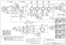
Also, speaking of switching only heaters. I want to ask what if I only switch one heater instead of both?
Here is the schematics, pin 4 and pin 5 are heaters. Pin 5 shows 9 volts while pin 4 is 0 volts. Does this mean that if I use relay only on pin 5 and leave pin 4 connected all the time, only with one relay I can switch the tube? because pin 4 is already connected to the ground....
So if this works (using one relay on one heater (pin5) I can switch tubes with 3 relays in total for 3 tubes)
if not, 6 relays... What do you think?
An externally hosted image should be here but it was not working when we last tested it.
Of course you only need three relays (actually you can do it with 2 relays, similar to the drawing I posted). You only need to break the connection to one end of the heater and it will go cold.I can switch tubes with 3 relays in total for 3 tubes)
However, your lack of experience tells me you should not waste your time with this switching project. If you don't know how to connect up three relays, you're not realy to build a three-tube switching project.
Build a single-tube circuit first, and get it working. Then tweak it; plug in different tubes; play with it; get bored with it (you will). I think you will find that a learning experience, without making it even more complex and expensive right from the start. Try the Valvecaster:

I also recommend you go to a forum more suitable for this topic.
http://www.diystompboxes.com/smfforum/index.php?board=2.0
Last edited:
Of course you only need three relays (actually you can do it with 2 relays, similar to the drawing I posted). You only need to break the connection to one end of the heater and it will go cold.
However, your lack of experience tells me you should not waste your time with this switching project. If you don't know how to connect up three relays, you're not realy to build a three-tube switching project.
I have lack of experience but I am a fast learner, I am trying to catch up actually, thanks to you guys...
More than making the pedal, learning electronics, how to connect relays and stuff makes me more excited I think... That's why I am here, to learn I have also seen the valve caster that you have suggested, previously. I hardly decided between the one I am working on and valve caster.
So here is my final drawing on the subject. I am attaching the relays to the 5th pins only as seen on the drawing...
An externally hosted image should be here but it was not working when we last tested it.
Again, thank you every one

PS: One of the relays, (the one which will be on when I power up the pedal) will be connected to NO instead of NC. I have not decided which one yet so they are all connected to NC...
Last edited:
- Status
- This old topic is closed. If you want to reopen this topic, contact a moderator using the "Report Post" button.
- Home
- Amplifiers
- Tubes / Valves
- Switch between tubes with relay