Okay - the NE5532 is definitely a much faster opamp than the 4558, so one might expect a few more problems. Before tearing into the general circuitry, it would be best to determine if the opamps are properly bypassed, with capacitors close to the opamp power pins. What sort of bypassing is used on this board? Is there any at all?
Also, do you have any scope pictures of the purported oscillation?
Also, do you have any scope pictures of the purported oscillation?
Last edited:
This was the original thread as I recall. chinoy posted some shots in the first 20 posts or so:Also, do you have any scope pictures of the purported oscillation?
https://www.diyaudio.com/community/threads/ne5532-preamp-questions.388300/
If you remember my post I had one board which worked clean and all the others had the osilations. So I opted to make the clean board my test jig.
And to test the op amps from the boards that were oscillating. Guess what I found. ?. All my op amps were clean in the test jig. So then I started to look at the components. And the board that worked had this 30 Pf cap between pins 6 and 7 and 2 and 1.
But in your post you say you cured it by putting a 5pf between R33 so basically your saying pins 2 and 6.
This has confused me.
Adding a cap between pins 2 and 6 (or pins 1 and 2 because it is a dual opamp) is a simple technique to reduce the gain at higher frequencies, the values used though depend on external component values and the opamp itself.
In your original thread I think you mentioned one channel having this issue which really made me wonder if there was some issue with the layout or even an error in the layout somewhere.
Wojahowski!And a generatorski, an AC voltmeterski!
That's certainly a common cause. Another cause can be the internal compensation of the opamp to make it unity gain stable. The OPA1611/1612 is an example. As are many of the other modern OPAxxxx opamps. I've seen significant ringing in differential amps that used the OPA1612 where the same circuit performed cleanly with the LME49720. I've also had the OPA1612 absolutely lose its mind (i.e., not even land at the correct DC operating point) in a GIC filter where the LME49720 and LME49860 were happy as can be.Oscillation is often a function of feedback resistor and input capacitance.
The phase shift caused by the RC makes the op amp an oscillator.
The OPA1612 and LME49720 are both good opamps and pretty similar in many respects. But dissimilar in their internal compensation. This is evident in the open-loop phase curves for the two parts. For the LME49720 the phase declines smoothly towards -180º. The phase of the OPA1612 has a wobble in it that can challenge compensation. Aside from that one GIC filter I've never had an OPA1612 that I couldn't make play nice with a cap across the feedback resistor, though.
Great thread! And great job of resurrecting it.
")
Tom
If you can't afford a screwdriver and need to fix a screw you are also screwed.So now we're arguing about exactly how much money we may or may not have?
Simple question pf range caps between pins 6 and 7 and 2 and 1. Or PF cap between Pins 2 and 6.
Which way is the right way and why.
This circuit no matter how basic. Is the only one that performs flawlessly. I have tried all the recommendations on the other boards and nothing helped.
The other boards have decoupling caps on the Opamp. i.e. soldered between pins. Did not help. (Even here I am confused some books say the 100 nf cap should be placed between +V and ground and -V and ground. And some books just call for a single cap between pins 4 and 8. I have tried both and it did not cure my problem.
It was never one channel. On boards with the oscillation both channels oslated.
Off the boards with the oscillation problem there is one which is a parametric equalizer that I really want to use but first I need to solve its oscillating problem.
I do not have a schematic for that board. But I do see it is missing the PF range cap.
Simple question pf range caps between pins 6 and 7 and 2 and 1. Or PF cap between Pins 2 and 6.
Which way is the right way and why.
Simple answer...
You need both. Pins 1, 2 and 3 are for one complete opamp in the package and pins 5, 6 and 7 are for the other opamp.
You can pick up a simple PC USB scope on ebay for peanuts that will be good enough for audio.I don't like being brow-beaten (esp. by a moderator!) into spending $150-200 minimum on a tool that might get used once a year. Seriously. Is that unreasonable?
(One of NP's early articles, A40, even has a suggestion on how to check DC at the outputs for the DIYer who HAS NO volt meter....!)
Or even a handheld unit.
Generatorowski!And a generatorski, an AC voltmeterski!
Hello,Sorry to dig up this old post. But I am reading up on how to resolve my osilation problems.
Just some observations.
1. Some people swear that the sound is improved. With the oscillations. In double blind tests they pick the board with osilations every single time. My OCD doesn't care about the sound I just want a clean signal. I even had a friend tell me that the osilations are part of the magic. lol
2. If you remember my post I had one board which worked clean and all the others had the osilations. So I opted to make the clean board my test jig.
And to test the op amps from the boards that were oscillating. Guess what I found. ?. All my op amps were clean in the test jig. So then I started to look at the components. And the board that worked had this 30 Pf cap between pins 6 and 7 and 2 and 1.
But in your post you say you cured it by putting a 5pf between R33 so basically your saying pins 2 and 6.
This has confused me.
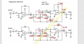
Please find attached the circuit of the board which works for me. The stuff marked in red are changes I found on my board. My board also uses the NE chip not the 4558.
This board works with zero oscillations the only problem is the Mids control is not so good need to work on that.
This circuit is fundamentally unstable and will be problematic.
The circuit is loading the inverting input with a capacitance to ground on the treble control, so the noise gain is very high and you are introducing significant phase shift. This is going to make the opamp you use critical, and the problem will be worse with high GPBW opamps like the OPA or LME devices. I think this circuit would work better if the main gain elements were single transistors where the overall loop gains would be much lower.
I've snipped the treble circuit out and done a quick analysis to show you what's going on here:-
To mitigate this problem, you can insert a resistor in series with the 'altos' pot wiper - try 100 Ohms, that should help. (I used the LT1115 because it is a high loop gain opamp, so will show this problem up more easily)
Thanks so much. I learn so much on this forum.
In a small way or paying back. A short story of my scope journey. 20 years back I could not afford a scope. So I purcahsed a sound card. We removed some caps on the Mic line and we used that as a scope.
My first real scope was a Fluke Meter 105b 100 Mhz portable dual storage scope purchased 2nd hand on ebay for 300$.
A few of the keys did not work. And the display was dim. I used that for like 15 years. Then a friend who helped me with my electronics developed such an aversion to my Fluke with with its faulty keys and weak display. That he said he wouldn't be helping me till I got a better scope.
So my savings and my research started. I spent months or a year+ to get it right knowing this would be my last scope Id purchase in this life time.
I finally decided on the Hantek DSO5102P Digital Oscilloscope. Which I was able to source brand new for 140$.
Am very very happy with this purcahse. Not only is it a 100 Mhz scope but you can upgrade it to 200 Mhz with just a firmware update.
Its no fluke. So I still sometimes dig out my old 105B if I need to confirm values. But last month a customer gifted me a Fluke 233 so that gets used more often for verification checks. One advantage of the 233 other than its detachable display is that you can calibrate it.
Getting back on subject.
The Rockola Scircuit. Which I will include here works the best i.e. zero oscillations. My friend says it sounds really good except for the mids and he wants me to try different cap values to see if the mids can be improved. He feels the mid control is not acting on the mid band but more on the high band.
Anyway as it works with zero oscillations I do not wish to tamper with it.
I would rather get my other tone control boards working. One is the Vasp board and the other is a parametric Eq by Xtreme amps.
I have a circuit for the vasp. I dont have the schematic for the Parametric and I am in the process of making a schematic for it. The fact that its been painted over to hide the circuit makes it a bit hard.
Bluejay with mid (Vasp) is oscillating. Rockola is not. Black text in rockola-salcon is original values red is values the board was sold to me with. The parametric board I am still trying to make a schematic off.
I could have just walked into a shop and purchased something instead I took the funds and purchased 3 pre-amps with tone control boards, 3 amp boards, and got stuck into a new hobby. Sadly most of the guys making and selling these boards in my country do not own scopes. So people either use them as is. Or they buy a few and pick one that sounds the best. My ultimate goal is to build my own parametric tone control board where I can control the Q and the Freq. These boards are just part of the learning process.
The other project Im trying to build is a Pre-Amp for my Akak HT350 turn table. Im having a tough time deciding weather I should go with a Pre-amp designed for MM turntable. Or to go with a generic pre-amp built for headphones. I have a collection off about 10-15 circuits of each type culled from old Elektor mags and stuff found on google. Studying each is in itself a learning exp. I like to enter up my ideas in a spice simulator.
Attachments
Last edited:
I want to add that some circuits may be stable under normal conditions but under other certain conditions no. They are marginally or conditionally stable. For example: it may be stable at, say; +/- 12V at power pins but no stable under +/- 15 or 9V. Sometimes the circuit is stable but with low voltages no, thus when switching it on, the thing starts to oscillate but once it started, it continues doing although the voltage has reached its normal voltage level.
Another word for this case. It is known between engineers that an oscillator is done feeding part of its output to the input with such a phase and amplitude that the amplifier feeds its own signal. But there is a less known theory that says that letting the amplifier can regenerate without enetring formerly to oscillate, but in such condition the output is the noise captured by the the circuit and amplified myriads of times and filteted by the frequency selective network. Once in the university I myself did a practical demostration of this theory said in cathedra.
I took a Wien bridge oscillator made with a simple TL081 and adjusted just to start oscillating, say, close loop gain 0.99999 but no 1. Then we feed it with an adjustable amount of noise created by a 1uF electrolytic reverse polarized and loaded with 100K to one power line. The result was a large sine signal at the output that could be larger enough to cause it to clipp, a fact that didn't occur in normal oscillating conditions.
Thanks you so much for the insights. Esp to Mooly I have been reading and reading and in almost every post he is there. Helping somebody. No negative attitude or vibes. A true Shaman of the tribe.
This video helped me a lot I hope it helps somebody. Im working on a post which outlines concepts one must understand for me impedance was one of them.
Yes mooley I will do that i.e. go step by step one opamp to the next. Im still struggling to make the schematic. So I have it ready when I start debugging.
Osvaldo de Banfield made a fair point. I should chk with various voltages.
I neat experiment I do when I'm bored is "noise browsing".
If the OP gets himself a nearer digital scope and keep on zooming into parts of his 1Khz tone he will be horrified with what he finds.
On audio foolery. If it's over 20K filter it out. It's garbage. Your quest for more is pointless, wasteful and sad.
Similarly, swapping opamps without the slightest understanding of how they work. Is also a fools game. If you don't understand how they work you will not be able to test IF they worked or not. If you did understand how they work you would probably know it's not worth doing anyway and if you do insist on doing so you will need to reconsider the WHOLE circuit. Opamps are not digital. They do not work alone, ALL circuit surrounding, upstream and downstream is involved in what it's doing. You change one part, you change the whole circuit response. Sometimes in rather unexpected ways.... most you won't hear anyway, it will just put wear and tear on your hardware amplifying garbage you can't hear anyway.
OP: Why are you not LPF'ing the output of the DAC before amplifying anything?
Thanks for your thoughts @paulca although I suspect you may have missed the point of the thread which was simply to point out to all those looking to swap and change their opamps to be aware of the problems that can occur.
Why would I? This is a highly regarded commercial product with an enviable reputation for its subjective sound quality. The thread was not specifically about modifying this unit, the player was just a convenient vehicle to use for the purpose of the thread.
which was simply to point out to all those looking to swap and change their opamps to be aware of the problems that can occur. OP: Why are you not LPF'ing the output of the DAC before amplifying anything?
Why would I? This is a highly regarded commercial product with an enviable reputation for its subjective sound quality. The thread was not specifically about modifying this unit, the player was just a convenient vehicle to use for the purpose of the thread.
I finally decided on the Hantek DSO5102P Digital Oscilloscope. Which I was able to source brand new for 140$.
Am very very happy with this purcahse. Not only is it a 100 Mhz scope but you can upgrade it to 200 Mhz with just a firmware update.
I'm going to be harsh here. Only because I made the same mistake 3 times.
You do not have a 100Mhz scope. You definitely do not have a 200Mhz scope. I will bet you a crate of beer it's probably barely a 30Mhz scope.
The reason is none of the budget scope companies actually "characterize" their scopes and report the test figures. Instead they take the raw hardware (ADC / SRAM / DSP) marketing specs and slap them on the box.
Sure it probably has an FPGA+ADC capable, on paper of 2Gs/s, although for a scope sold with 200Mhz bandwidth in that market it's probably only 500Ms/s or 1Gs/s Either way, the front end analogue bandwidth (3db drop) is usually an order of magnitude lower than the headline ADC figure.
I bought an OWON 20Mhz scope which I tested and it did 5Mhz.
I bought a 5Mhz mini hand held and it does about 500KHz - you can't debug an 800KHz PWM waveform with it!
I bought a Yeapook 100Mhz scope and it craps out about 30Mhz. By about 70MHz it's not even showing a basic approximation of the signal, it has DC offsets, aliasing and even mathematical display errors.
"They are fine for audio" is something you will hear. The thing is, you can't scope audio. If you have ever tried you'll quickly realise it's pointlessly difficult. Because it's not a consisent, repeating signal. So they scope can't do anything but single trigger on a small part of the wave. On a digital scope, even a bad one you will find most of the signal is just noise. The actual audio is just an undertone onto which the noise is modulated.
The Yeakpook was the last straw. When I tried to look at a 24Mhz I2S clock with it and it showed me a 50Hz modulated 24.576Mhz sinewave which it claimed was at 500Khz.
I used 6 months interest free credit on Amazon and bought a Siglent SDS1104Xe. All I can say is WOW! The difference is not even night and day it's far more than that. A proper characterized 100Mhz scope is actually capable of measuring 2 or 3 times that with some degradation. 100Mhz is it's 3db cut off point. If you are happy to accept 6, 9, 12db loss you can measure signals up to 400Mhz. Hell I could see and measure harmonics close to the GHz band.
This suddenly makes the whole situation change. Your square wave 12Mhz clock signals you were so proud of are actually found to have 2Vpp ringing at 100Mhz creating a total Vpp of your clock to be well over twice your digital domain system voltage.
You start to see the I2S clocks and processor clocks modulated onto your audio signals via EMF/RF/Coupling.
You also find that 90% of how useful a DSO is is found in the functionality and ease of use of it's software. The SDS has pages and pages of trigger settings. However with the Yeapook, I couldn't even delay trigger on an I2S stream to see the second byte. There just was not way to have the resolution AND the memory depth to see the second byte. You could zoom out and see two bytes, but not enough resolution to see the individual bits. Zoom in and you could only see the first byte. It's like a toy literally in comparison.
Of course the downside. The SDS1104Xe "which can be hacked to 200Mhz and has an actual 200Mhz bandwidth analouge front end"... was... £440 delivered.
You should probably get a (not TOO cheap) signal generator and characterize your scope, I think you'll be disappointed.
- Home
- Source & Line
- Analog Line Level
- Swapping Op-Amps... you have checked to see it's stable haven't you ?