I receive my board yesterday. Thank you Dirkwright!
That's great. What are you going to use for a power supply? I have some boards made up for the LM78XX/LM79XX chips. I have also ordered some boards for a transformer driver circuit for a balanced, isolated output. Output level can be controlled with a simple 1k pot on the output of Glen's board.

Fired it up - the oscillator swings and all frequencies seem to work.
Trimming and test (need better sound card) scheduled for later.
That's great!
I don't know how to adjust the trimmers. Can you share what you learn?
From what i understand so far.
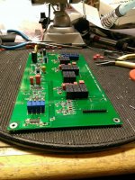
The group of 4 trimmers (far away in my pic) is simply frequency adjust. Trimmers closest are rectifier balance. Since input to rectifiers is take after first integrator and second integrator that are 90 deg. apart and respective signal is then inverted 180 deg. we get four phases. These trimmers adjust balance between the 'phase pairs' that is sourced from first and second integrator, i.e. rectifier balance. It will be interesting to look at the rectifier output.
As for the single trimmer far left i think Glen's page explains it best (previous version, 8 Jan update): An Ultra Low Distortion State Variable Oscillator
Last edited:
Hi,
Frequencies adjusted, ~ 2-3Hz tolerance within each group. Then i checked the fft on the rectified output (tp2) and was able to null second harmonic on each frequency group.
As for the rest i need better test equipment.
The oscillator takes about 75mA@12V (+/-) no output load. The relays (frequency selection) at most ~260mA@6V.
Hi dirkwright,
To be honest I made it difficult for myself. 15 years since any SMD work, no clip/clamp and no magnifying glass (that I really need nowadays).
I had in mind making a diy clamp but did not get so far. Like this: DIY clamp helps with surface mount soldering well, perhaps it should be a little more sophisticated but just to show the idea.
Hi dirkwright,
To be honest I made it difficult for myself. 15 years since any SMD work, no clip/clamp and no magnifying glass (that I really need nowadays).
I had in mind making a diy clamp but did not get so far. Like this: DIY clamp helps with surface mount soldering well, perhaps it should be a little more sophisticated but just to show the idea.
 HAHA, that's a funny looking thing! Thanks.
Yes, I find it funny looking as well.
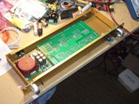
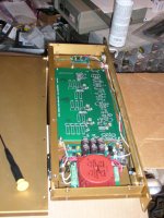
Nice case you have, almost perfect sized for this application. I seems like a unbalanced output at the back panel. Do you plan to place the mixed feedback circuit in a separate box?Yes, I find it funny looking as well.
Until I can figure are truly low distortion single ended to balanced converter, I'm not using anything. I designed a basic buffer using one LME49710 and one BUF634 and am waiting on the circuit boards. So, that little board will fit in the box and provide a really low and consistent output impedance for the oscillator. When, and if, I figure out a really low distortion converter, then I'll make another box for that. The all solid state one I have in my simulator uses 8 chips! I'm not sure I want to use it though.
The box I'm using is from Par-Metal.
Par-Metal
It is RFI resistant. The small box I got costs about $100. I'm impressed. It is very well made.
Do you guys have any measurements?
I think Glen found that he could not measure any distortion at all, but that he needed better equipment. So, it should be pretty good at least.
I am away on holidays now and I just saw this thread. Any boards left, if so I would like one.
Thanks
They are all gone but Glen has the Gerber files up on his website.
- Status
- This old topic is closed. If you want to reopen this topic, contact a moderator using the "Report Post" button.
- Home
- Group Buys
- SV Oscillator PCB group buy