Look in the chip datasheet!
TA2024/TA2021B: Bridged (Stereo)
TK2050:Bridged (Stereo)/Bridged+Parallel(Mono)
TA2020:Bridged (Stereo)
TA2022:Single ended (Stereo, Bridgeable to Mono)
TA3020:Single ended (Stereo, Bridgeable to Mono)
TAA4100A: Bridged (Four channel, can be Paralelled)
TK2350: Single ended (Stereo, Bridgeable to Mono)
So you'd best take 35V caps for the TA2024, 100V caps for the TK2050....
are the mods similar on the 2024c version? or any experience with this one, i cant see c3 or c24 on the board in the pic,,
2*15W TA2024C Tripath Digital Class-D Amp + 12V adapter - eBay (item 220665410782 end time Oct-06-10 02:07:55 PDT)
2*15W TA2024C Tripath Digital Class-D Amp + 12V adapter - eBay (item 220665410782 end time Oct-06-10 02:07:55 PDT)
Hi, hard to say without having one. You should use a DMM to check the layout, (like trace from input resistors to input caps) or kindly ask Sure for the circuit drawing.
As for TA2024C, my last PCB came with this and not with the former TA2024, no more R3/R16 wich where in most case a problem more than a fix.
But, I have a 43mV DC on one channel, I don't know if it's OK to live with or not? Anyone ever fried a speaker with such DC?
Also the ouptut caps are different, these SMD are half smaller.
I wanted to use amps at speakers to bi amp but seems I must use one amp for highs and one for low as they are not the same.
OK, I find the solution:
http://www.diyaudio.com/forums/clas...w-class-d-amplifier-board-11.html#post2013613
Thanks to audio1st and craigwn, It works perfectly know, dc offset are after adjsutement:
-15mV
5mV
2mV
0,2mV
http://www.diyaudio.com/forums/clas...w-class-d-amplifier-board-11.html#post2013613
Thanks to audio1st and craigwn, It works perfectly know, dc offset are after adjsutement:
-15mV
5mV
2mV
0,2mV
")
I'm having a problem with the sureelectronics amp.
I've done the cap mod by removing C3 and C24, and the amp worked fine.
Today, I removed and bridged C13 and C21, and now my amp no longer works.
If there's nothing plugged in to the amp besides the power and a multimeter on the speaker side, I get about a 10 millivolt DC offset, but the second I plug in an input the DC offset shoots to 12 volts.
I'm using a 12 volt regulated power supply. Has the amp gone bad?
New board revision!!
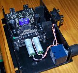
Hi i received my amplifier yesterday, i plan to squeeze it in an Lepai LP2020 Case. So i can have a 4 channel amp in a really small case ;-). The sure will drive the front speakers in my car, the lepai is used to drive a small sub.. and it does it well for ~1,5 years.
It will fit, but with heavy modifications. And what i noticed, i got a new revision of this board. Looks a little bit different, with dc-offset potentiometers too! It came adjusted (15-20mV), but now i am almost at 0,0 mV per channel. I am not sure if i need to change the input caps.
An externally hosted image should be here but it was not working when we last tested it.
Uploaded with ImageShack.us
Hi i received my amplifier yesterday, i plan to squeeze it in an Lepai LP2020 Case. So i can have a 4 channel amp in a really small case ;-). The sure will drive the front speakers in my car, the lepai is used to drive a small sub.. and it does it well for ~1,5 years.
It will fit, but with heavy modifications. And what i noticed, i got a new revision of this board. Looks a little bit different, with dc-offset potentiometers too! It came adjusted (15-20mV), but now i am almost at 0,0 mV per channel. I am not sure if i need to change the input caps.
An externally hosted image should be here but it was not working when we last tested it.Uploaded with ImageShack.us
exactly my question... anyone?
Bypass the input caps if you've got it at zero.
Aaaaand kaboom.... dead chip...
The thing is... I can not locate the input caps...
The input caps are a shy ceramic pair on this amp, almost feel ashamed to call them capacitors. They are the first components the input signal will see...
You can choose a better alternative, like a nice polyester capacitor rated at 63Vdc and 1uF. Don't go ridiculous on oil drum sized kilovolts rated nonsense caps is my advise....
- Status
- This old topic is closed. If you want to reopen this topic, contact a moderator using the "Report Post" button.
- Home
- Amplifiers
- Class D
- Sure Electronics Tripath boards?