I looking to build a case for my sure 2X100 amp. My fan is noisy, will a passive heat sink work or should I get a new/better fan. The speakers I am running are pretty demanding 4 oHm design. What passive heat sink are you guys using. I just spent about an half an hour using the search feature with no luck.
Thanks
Thanks
Originally Posted by teamacc

1. Remove input suppressors (underside of the board, look like smd diodes)
2. Replace input caps (audio1st has a great tutorial picture)
3. Use 32v
4. Remove the fan and replace the heatsink with a zm-47j northbridge cooler
5. Replace output filter, some wurth xxl coils fit right in the original space and sound great, search this thread for wurth xxl to find them
6. Replace buffer caps
7. Replace output caps
Number 1 is most important, while number 7 is least.
Might be not in (complete) correct order, but if you get to 5, you might as well do 6 and 7.
Just quoting myself
Hope this helps
Hi,
I wonder if it is advisable to change 6 capacitors on the board rated at 330uf 50v to 470uf 50v Nichichon Muse?
What are those 6 capacitors for?
Regards
Hi! i have just ordered the 2x100w version and the mean well 36v 350w psu.
What upgrades should I do to the amp? This will be my first DIY amp and I need all the help I can get. Url to the upgrades are highly appreciated.
If you have any sugestions for a budget bookshelf-speaker set (diy) as well, I am interested in building a set. I live in Norway, and the shipping costs are usually higher than the item cost on most items :/
Sorry about my poor english.
I appreciate ALL help
What upgrades should I do to the amp? This will be my first DIY amp and I need all the help I can get. Url to the upgrades are highly appreciated.
If you have any sugestions for a budget bookshelf-speaker set (diy) as well, I am interested in building a set.
I live in Norway, and the shipping costs are usually higher than the item cost on most items :/ Sorry about my poor english.
I appreciate ALL help
Hi! i have just ordered the 2x100w version and the mean well 36v 350w psu.
What upgrades should I do to the amp? This will be my first DIY amp and I need all the help I can get. Url to the upgrades are highly appreciated.
If you have any sugestions for a budget bookshelf-speaker set (diy) as well, I am interested in building a set.
Sorry about my poor english.
I appreciate ALL help
Did you ordered from partsexpress?
Just few days ago I recieved 2 orders from them 120$(resistors, capacitors) and 180$(tweeters) and there were no tax
The same day come midrange drivers from Denmark web store 1100 nok with 570 nok tax
What gear do you have now?
I started diy influenced by amazing lampizator guy, I advise to read it. Its little about amps, but its good about ideology.
Lukasz Fikus Lampizator
You have to remember that diy is not about changing to expensive parts. You will find many information in this thread, many about changing input capacitors and output coils, but there will be no much improvement, realy.Thats becouse you will be limited by speakers and source.
I have ta2020 amp, lower power, and its sounds amazing, there will be no coming back. I have Jamo D450 speakers with top noch vifa xt drivers and heavy modified cd player, and when I put this amp in my chain I coulnt believe how good it sounded, just astonishing.
Experimented to put my old JBL LX2005 speakers and there were no difference between mid class av reciever. Tryed sony sacd player with elna silmic II stock caps inside and difference was realy, realy huge- no music just sound.
What I want to say is that most likely "sure" amp will be the best part of your system, yes it has not the Best parts availible, but its very minimalistic design.
Its not the answer what you was looking for, I see you are eager to diy something, but firstly wait till your amp arrives, pay tax, connect and enjoy your music and read this thread
Please can someone explain how input cap makes high pass filter if the resistor is in series with capacitor, not like in picture to the ground?
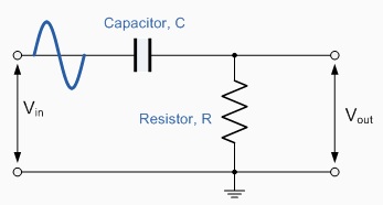
It won't, if it's connected like (source)----||----vvvv----(nothing)
(Hmm the resistor didn't show up too well in ASCII art.)
However, real inputs have a finite impedance to ground, so it'll still end up like the picture you posted.
Add the series R to the input impedance. This will give you the R value you need to calculate the filter corner frequency.
A simple voltage across resistors in series calculation will tell you how much of the signal voltage is across the series R and how much across the input. Usually most of the voltage will be over the input, as the input impedance will typically be much higher than the series R.
A simple voltage across resistors in series calculation will tell you how much of the signal voltage is across the series R and how much across the input. Usually most of the voltage will be over the input, as the input impedance will typically be much higher than the series R.
Add the series R to the input impedance. This will give you the R value you need to calculate the filter corner frequency.
A simple voltage across resistors in series calculation will tell you how much of the signal voltage is across the series R and how much across the input. Usually most of the voltage will be over the input, as the input impedance will typically be much higher than the series R.
Here I can calculate corner frequency
Guitar Pedals: R-C Filter Calculator
Butterworth Pi LC Low Pass Filter Calculator
In these calculators you enter input resistor impedance and capacitor value, easy, but these pictures confused me.
Corner frequency is the same for high and low pass, but I cant take out cap make low pass insted. So if I want to make line level low pass filter for woofer, it will eventualy be band pass filter?But bigger cap and its done.
But band pass would be great for 2nd board with midrange cannected
So how I can add low pass?
http://content6-foto.inbox.lv/albums177796062/roxis86/12-11-2011/pass-band-1.png
Add some resistor before input cap and capacitor paralel to input resistor?
Which value of resistor should I choose?
Thank you for support!
It won't, if it's connected like (source)----||----vvvv----(nothing)
(Hmm the resistor didn't show up too well in ASCII art.)
However, real inputs have a finite impedance to ground, so it'll still end up like the picture you posted.
Read it in another thread
Originally posted by Dartagnan
"I was thinking the interaction of the cap with the amp input impedance was what determined the frequency--but this is not so?
Basically the input impedance of the amp is so high that the impedance of the filter is dominant. This is why passive filters are a bit tricky -- you need to make sure that the load impedance is going to have negligible effect on the filter."
Load impedance is source or volume attenuator ? 10k Ladder type in my case has variable impedance output depending on volume, it can interact with corner frequencies somehow?
Hi
Mine came recently. I checked it out & guess what ? Right channel has 16v dc offset & the left is at the normal 13mv value. If i put this board to work with speakers it will destroy the right one. I'm very disappointed . I asked sure to send it back. Lets see if they are good professionals.
Very bad, you need to check everything before you put it in your system.
Vassilis
Thanks. I hope everything ends up fine. About the board i will send it back and wait for a new one or a refund after they contact me via the resolution center..
Lets see how it goes. I was very enthusiast from all these reviews. I hope i'll finish this diy project soon.
As for the very high offset i was wondering what is causing it.
Lets see how it goes. I was very enthusiast from all these reviews. I hope i'll finish this diy project soon.
As for the very high offset i was wondering what is causing it.
Sure send me an email today and advised me to adjust either the R16 and R35 for the DC offset, which i will do in a few hours.
But i have a question here. Is it possible for this board to produce such high 16v dc offset on one channel as mine is doing?
Left channel has: 13mv dc , Right channel has : 16v dc (plus high frequency noise)!!!! Straight out of the box. Very lucky that it did not destroy my right speaker .
I hope that if I adjust the offset from 16v down to 13mv it will be OK. Otherwise there must definitely something wrong with this board.
Any help will be appreciated here.
Vassilis
I'm on a 24v dc power supply. I've tested it and works with other projects i have without problems.
I'll test continuity tonight. The board has been tested bare , on my isolated desk. There is no chance to short it. I'm just curious to see why sure-electronics suggested me to adjust the dc offset via the resistors and did not give me details to send it back to them.
If the offset on the right channel drops from 16v dc to 13mv after the adjustment i'll go to a church close to my house and light a candle....
Now the bad news.
Left channel is fine. Offset can be adjusted close to 0mv. Right channel has inverted polarity (??) and measures from -15.45volt to -17,5volt. I do not intend to do anything else with this board. I will ask them for a replacement or even my money back. I should have bought the one from HIFImidiy . At least the their support even in this forum is perfect.
Left channel is fine. Offset can be adjusted close to 0mv. Right channel has inverted polarity (??) and measures from -15.45volt to -17,5volt. I do not intend to do anything else with this board. I will ask them for a replacement or even my money back. I should have bought the one from HIFImidiy . At least the their support even in this forum is perfect.
Good news.
Sure customer support contacted me. Gave me details how to do some measurements with a multimeter on the amp . Asked for the results and agreed that one channel on board is broken. A person called Skeeter told me that they will send me a new board without further questions. I would like to congratulate them for that. There is really good support from this company.
Sure customer support contacted me. Gave me details how to do some measurements with a multimeter on the amp . Asked for the results and agreed that one channel on board is broken. A person called Skeeter told me that they will send me a new board without further questions. I would like to congratulate them for that. There is really good support from this company.
- Status
- This old topic is closed. If you want to reopen this topic, contact a moderator using the "Report Post" button.
- Home
- Amplifiers
- Class D
- Sure Electronics New Tripath Board tc2000+tp2050