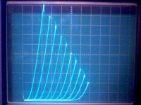
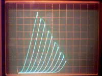
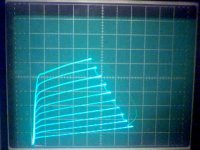
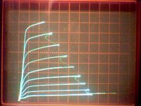
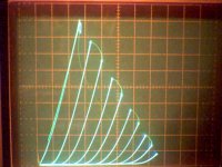
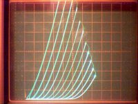
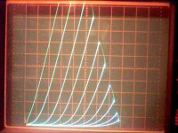
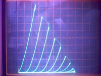
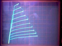
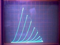
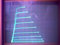
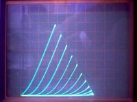
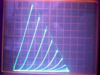
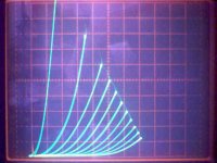
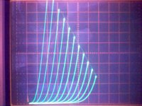
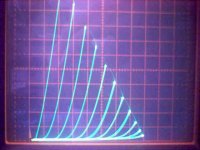
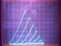
Here is 12L6 in triode mode with an optional resistor in the g2 connection to plate. 10 mA/div vert. , 50V/div horiz., 5.5 V/div steps on g1.
Plot 1: no g2 resistor, direct g2 to plate conn.
Plot 2: 10K Ohm g2 resistor to plate
Plot 1: no g2 resistor, direct g2 to plate conn.
Plot 2: 10K Ohm g2 resistor to plate
Attachments
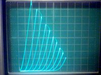
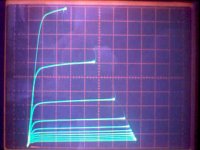
Next up is 24JZ8:
Plot1: pentode mode: 10 mA/div vert., 50V/div. horiz., 100V on g2, 1.4V per step on g1
Plot2: triode wired: 10 mA/div vert., 50V/div horiz., 5.5V steps on g1
Plot3: g2 drive: 10 mA/div vert., 50 V/div horiz., 5.5V steps on g2
Plot4: the actual triode in there: 5 mA/div vert., 50 V/div. horiz. , 2.6 V steps on g1
I think there is a nice GE datasheet on the 6JZ8 at Franks.
No problem on sockets, I have pin jack leads that will fit the ECF200 and clip leads for the GU-50
I've never seen a 10 pin tube before! Looks like it would be a good joke to give someone to try fitting it into a 9 pin socket.
I have a Sovtek 6L6WXT here if you want to see some triode curves.
Attachments
Last edited:
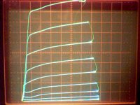
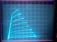
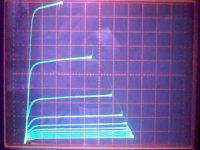
Here is 6L6WXT:
Plot1: pentode mode: 10 ma/div vert., 50 V/div. horiz., 2.6 V steps on g1, g2 at 150 V
Plot2: triode mode: 20 mA/div. vert., 50 V/div. horiz., 5.5 V steps on g1
Plot3: g2 drive: 5 mA/div vert., 50 V/div horiz., 5.5 V steps on g2, 0 V on g1
Plot1: pentode mode: 10 ma/div vert., 50 V/div. horiz., 2.6 V steps on g1, g2 at 150 V
Plot2: triode mode: 20 mA/div. vert., 50 V/div. horiz., 5.5 V steps on g1
Plot3: g2 drive: 5 mA/div vert., 50 V/div horiz., 5.5 V steps on g2, 0 V on g1
Attachments

Next up is 24JZ8:
Plot1: pentode mode: 10 mA/div vert., 50V/div. horiz., 100V on g2, 1.4V per step on g1
Plot2: triode wired: 10 mA/div vert., 50V/div horiz., 5.5V steps on g1
Plot3: g2 drive: 10 mA/div vert., 50 V/div horiz., 5.5V steps on g2
Plot4: the actual triode in there: 5 mA/div vert., 50 V/div. horiz. , 2.6 V steps on g1
I think there is a nice GE datasheet on the 6JZ8 at Franks.
No problem on sockets, I have pin jack leads that will fit the ECF200 and clip leads for the GU-50
I've never seen a 10 pin tube before! Looks like it would be a good joke to give someone to try fitting it into a 9 pin socket.
I have a Sovtek 6L6WXT here if you want to see some triode curves.
Actual triode in 24 JZ8 looks very nice, but a pentode section does not look ideal for SE, either in triode or pentode. It explains why I did not like it's sound in a hybrid driver, even CCS loaded trioded pentode as an output that drove MOSFET source follower. However, couple of them would rock in PP. Like triode LTP phase splitter and pentode output, 2 tubes only. Something like 10W in class AB, using cheap industrial transformers. Or, something like Fender output stage, for studio & practicing.
Last edited:
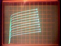
Here is GU50 (limited step range for this one here, can try g2 drive later when the curve tracer is up to it.)
Plot1: pentode mode: 50 mA/div vert., 50 V/div. horiz., 5.5V steps on g1,
200 V on g2, 0V on g3
Plot2: pentode mode2: 50 mA/div vert., 50 V/div. horiz., 5.5 V steps on g1,
200 V on g2, +14V on g3
Plot3: triode config.: 20 mA/div vert., 50 V/div. horiz., 5.5 V steps on g1
+14 V on g3, a nice fixup in pentode mode.
g3 best at 0 V for triode.
There is some 60 HZ hum effect in the triode curves causing grouping of double traces here. The 24JZ8 triode curves has some hum effect in there too I think.
Attachments

Last edited:
Here is GU50 (limited step range for this one here, can try g2 drive later when the curve tracer is up to it.)
Plot1: pentode mode: 50 mA/div vert., 50 V/div. horiz., 5.5V steps on g1,
200 V on g2, 0V on g3
Plot2: pentode mode2: 50 mA/div vert., 50 V/div. horiz., 5.5 V steps on g1,
200 V on g2, +14V on g3
Plot3: triode config.: 20 mA/div vert., 50 V/div. horiz., 5.5 V steps on g1
+14 V on g3, a nice fixup in pentode mode.
g3 best at 0 V for triode.
There is some 60 HZ hum effect in the triode curves causing grouping of double traces here. The 24JZ8 triode curves has some hum effect in there too I think.
Wow!
 Telefunken rulez!
Thank you for the tip about +14V on G3; it allows to squeeze all useful linear power from the beast!

I am going to try it in my Pyramid-V that I currently use in my living room, I have +12.6V there to power driver filaments.
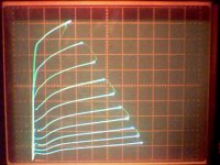
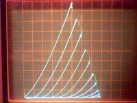
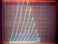
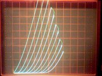
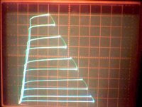
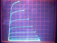
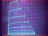
Here are the whole group together for comparison of triode mode curves.
1) 5763
2) 12L6
3) 24JZ8
4) 6L6
5) GU50
Yeah, there is noticeable hum grouping in the GU50 triode curves (notice at bottom, pairs squeezed), I'll try to redo them later.
1) 5763
2) 12L6
3) 24JZ8
4) 6L6
5) GU50
Yeah, there is noticeable hum grouping in the GU50 triode curves (notice at bottom, pairs squeezed), I'll try to redo them later.
Attachments

Last edited:
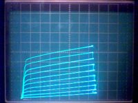
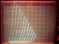
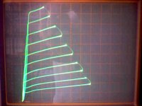
Re-did the GU50 triode curves, 2nd set is an enlargement of the bottom quarter of the 1st. And tried g2 drive, and it worked OK for the limited step voltage available.
Plot1: triode mode: 20 mA/div vert., 50 V/div horiz., 5.5 V steps on g1
Plot2: triode mode: 10 mA/div vert., 50 V/div horiz., 5.5 V steps on g1
Plot3: g2 drive mode: 10 mA/div vert., 50 V/div horiz., 5.5 V steps on g2, g1
at +4 V, g3 at +2 V
Plot1: triode mode: 20 mA/div vert., 50 V/div horiz., 5.5 V steps on g1
Plot2: triode mode: 10 mA/div vert., 50 V/div horiz., 5.5 V steps on g1
Plot3: g2 drive mode: 10 mA/div vert., 50 V/div horiz., 5.5 V steps on g2, g1
at +4 V, g3 at +2 V
Attachments
Last edited:
Tried to start on the 6F12P, but running into hum problems in the pentode curves now. (notice squeezed grouping by twos on left side) Triode mode came out not too bad surprisingly. I'll try again tomorrow when the tracer has cooled off. If I can't get rid of the hum problems, then I'll have to check the power supplies.
Plot1: pentode: 2 mA/div vert., 50 V/div horiz., 0.27 V steps on g1, 100 V on g2
Plot2: triode config. 1 mA/div vert., 50 V/div horiz., .55 V steps on g1
Plot1: pentode: 2 mA/div vert., 50 V/div horiz., 0.27 V steps on g1, 100 V on g2
Plot2: triode config. 1 mA/div vert., 50 V/div horiz., .55 V steps on g1
Attachments
Last edited:
Do you have any 7KY6 or similar frame grid pentodes? I did one once,
http://webpages.charter.net/dawill/tmoranwms/Data_7KY6.gif
This graph was made by compositing photographs, so it's not too accurate. Fairly linear, and you can't beat the gain or the price.
Tim
http://webpages.charter.net/dawill/tmoranwms/Data_7KY6.gif
This graph was made by compositing photographs, so it's not too accurate. Fairly linear, and you can't beat the gain or the price.
Tim
Do you have any 7KY6 or similar frame grid pentodes?
Right above: 6F12P
Still having problems with power supply ripple, seems to be more obvious on smaller scale factor plots. I think I will just put some binding posts on the back of the tracer for an external reg. supply. But in the mean time I will try to finish up the tube plots as best possible for now.
"Do you have any 7KY6 or similar frame grid pentodes? "
Sure do. Here are plots for a Magnovox (Japan) 7KY6, and an RCA 11HM7, which seem to be identical tubes except basing, & fil. I've got 12HL7 and 12HG7 too, which I'll add to the pile to do.
Then a couple more tries on the 6F12P
Plot1: 7KY6 pent. 10 mA/div vert., 50 V/div horiz., 100 V on g2, .25 V per step on g1
Plot2: 7KY6 triode mode 10 mA/div vert., 50 V/div horiz., 1.4 V steps on g1
Plot3: 11HM7 pent. ditto per 7KY6
Plot4: 11HM7 triode ditto per 7KY6
Hmmm, looks like the pentode curves are close but the triode curves are different. I'll have to recheck that one. May be just a DC bias adjust shift between plots. The tracer has an A:B compare switch so I will put them back in under same settings later to check.
Plot5: 6F12P pent. 2 mA/div vert., 50 V/div horiz., .27 V steps on g1, 100V on g2
Plot6: 6F12P triode mode 2 mA/div vert., 50 V /div horiz. .55 V steps on g1
Attachments
Last edited:
Re-did the 11HM7 triode curve to match up the DC bias with the 7KY6, looks better matched now, but the 11HM7 curves are leaning over more at the HV end.
Only got one or 2 of each type, could just be that tube. Would have to test a few to see if that is consistent or not.
Only got one or 2 of each type, could just be that tube. Would have to test a few to see if that is consistent or not.
Attachments
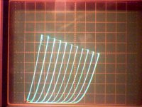
Next up, 6U9/ECF201 and 6X9/ECF200
Plot1: 6U9 pent. 2 mA/div vert., 50V/div horiz., 100 V on g2, .55V steps g1,
0 V on g3
Plot2: 6U9 pent. 2 mA/div vert., 50 V/div horiz., 100 V on g2, .55V steps g1,
+11V on g3
Plot3: 6U9 triode mode 2 mA/div vert., 50 V/div horiz., 2.75 V steps on g1
Plot4: 6X9 pent. 2 mA/div vert., 50 V/div horiz., 95 V on g2, .27 V steps g1,
0 V on g3
Plot5: 6X9 pent. 2 mA/div vert., 50 V/div horiz., 95 V on g2, .27 V steps g1,
+11V on g3
Plot6: 6X9 triode mode 2 mA/div vert., 50 V/div horiz., .55 V steps on g1
6U9 looks like remote cutoff. 6X9 looks nice.
Attachments
6U9 looks like remote cutoff. 6X9 looks nice.
Thank you Don!
- Status
- This old topic is closed. If you want to reopen this topic, contact a moderator using the "Report Post" button.
- Home
- Amplifiers
- Tubes / Valves
- Suppresor Grid used for Feedback?