Display
Hi,
thx for answering.
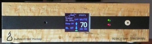
I think of something similar to the Hifiduino Project. Only with a better visible display-type. like i.e. these mark levinson products. The hifiduino uses an arduino and i do not see the need for an other microcontroller. the i2c lines could be isolated (as in Hifiduino project). Or would running some of the code produce "noise". I am testing some of adafruits alphanumeric 0,54" displays which look great. Also adafruit and embedded adventures have some nice small 8x8 led matrix displays. the visibility is superb. I wish for only the most important information on the "Front" display like Input, sample rate and Volume. other information about filter settings could be on second and third screen (showable by remote). I am in the process of "diy". but I am far away from success mostly on software side.
Noise: Is the problem having the display in the same case as BBB and dac or is it the data lines? I think of some sort of shielding the display inside the case and digital isolation for the connections to BBB. Maybe with separate power supply.
branko
Hi,
thx for answering.
I think of something similar to the Hifiduino Project. Only with a better visible display-type. like i.e. these mark levinson products. The hifiduino uses an arduino and i do not see the need for an other microcontroller. the i2c lines could be isolated (as in Hifiduino project). Or would running some of the code produce "noise". I am testing some of adafruits alphanumeric 0,54" displays which look great. Also adafruit and embedded adventures have some nice small 8x8 led matrix displays. the visibility is superb. I wish for only the most important information on the "Front" display like Input, sample rate and Volume. other information about filter settings could be on second and third screen (showable by remote). I am in the process of "diy". but I am far away from success mostly on software side.
Noise: Is the problem having the display in the same case as BBB and dac or is it the data lines? I think of some sort of shielding the display inside the case and digital isolation for the connections to BBB. Maybe with separate power supply.
branko
That's what I wonder, too. I have some optocouplers, but if the BBB and cape, or the display, were in a sub-case, or otherwise shielded, would noise on the power and data lines be the problem, or just interference from the LCD being close? I'm nowhere near a point where I can test it, myself.Noise: Is the problem having the display in the same case as BBB and dac or is it the data lines? I think of some sort of shielding the display inside the case and digital isolation for the connections to BBB. Maybe with separate power supply.
The LED matrices would either need a special driver board, or warrant another uC, if just to save wiring headaches. But, they're easy to control, since you're just pushing 1-bit pixels in one end, and they go out the other. No settings, commands, or any of that, like most LCD drivers have. You could also add more of them to the side, and then not need to page for more info, since most of them lack borders. The ones I have from Adafruit aren't what I'd call tiny, but they have pretty even color and brightness, so several of them side by side should look fine, run to similar current levels.
The LED matrices would either need a special driver board, or warrant another uC, if just to save wiring headaches. But, they're easy to control, since you're just pushing 1-bit pixels in one end, and they go out the other. No settings, commands, or any of that, like most LCD drivers have. You could also add more of them to the side, and then not need to page for more info, since most of them lack borders. The ones I have from Adafruit aren't what I'd call tiny, but they have pretty even color and brightness, so several of them side by side should look fine, run to similar current levels.[/QUOTE]
Maybe you take aloof here: Embedded Adventures - LED Matrix Display - LDP-3208S with tiny pixels (white)
These are chain able.
branko
Maybe you take aloof here: Embedded Adventures - LED Matrix Display - LDP-3208S with tiny pixels (white)
These are chain able.
branko
That would be one of those special driver boards. Adafruit's matrices would be roughly $16 for the same thing, as far as display portion goes, but leave you needing to work out how to handle the act of displaying data, which is where all the wiring could come in (it won't be any cheaper if you order controlling parts from them, but can be ordering from Mouser, Digikey, etc). Or, cost $40 for the same, with their own I2C boards.
OLED displays would be ideal, but it seems large enough ones, with easy to talk to drivers, just aren't sufficiently available.
OLED displays would be ideal, but it seems large enough ones, with easy to talk to drivers, just aren't sufficiently available.
As an alternative to a front panel display why not get the same information presented to you on a tablet/smartphone in the comfort of your listening seat? Oh, and be able to select what is playing from your network music library on the same device (and, I'm hoping, be able to control the volume too - presume that will need miero to release a Botic distribution with i2c).
I plan to use gmediarenderer over the top of miero's release to turn my BBB into a upnp/dlna renderer. I have already installed it on the previous distribution and the functionality all seemed to work (didn't actually listen as my DAC is a work in progress awaiting a Botic). Controlled via Bubble UPnP on my tablet, I get cover art, timings, file type (flac etc.), sample rate, bit depth, displayed as well as being able to select from the library, and so on.
The instructions in this blog worked for me (miero's distribution is debian based the same as this RPi install);
Playing music on a Raspberry Pi using UPnP and DLNA (v3) | Stephen C Phillips
Ray
Yes, that's my preferred method of operation.As an alternative to a front panel display why not get the same information presented to you on a tablet/smartphone in the comfort of your listening seat?
But it seems many people still like having some form of information display on the box-that-sits-next-to-the-amplifier. I think it's a familiar paradigm set by CD player-based hifi systems in the 1980's.
Even the pioneering SqueezeBox products maintained the idea of having the information display on the "base" unit.
Everyone's free to add their preferred flavour of media server / renderer / controller applications,I plan to use gmediarenderer ...
Controlled via Bubble UPnP on my tablet
but for the benefit of anyone new to this thread, Miero's OS image for the BeagleBone Black already contains MusicPlayerDaemon, which is a ready-to-go music server and renderer. All you need is a (standard) Network-Attached Storage device from which to access your music files, and then run a MusicPlayer Daemon client application on your preferred smart-phone or tablet computer. Different MPC clients are available for Android, iOS, OS X, Windows Mobile, Windows, and Linux.
The applications mentioned by nautibuoy, apart from their user interaction features, mainly add UPnP functionality, which simplifies connectivity between the different hardware components.
Without such additional software, MPD is still relatively easy to configure:
- you must configure the BeagleBone Black to mount your NAS device, then configure MPD to use this mountpoint as the "music_directory"
- on your controller device you must define the IP address where MPD is running - obviously this is the IP address of the BeagleBone Black.
That's it.
Thanks linuxfan, as the years march on the idea of having things brought to me is becoming increasingly attractive and, besides, my eyesight has deteriorated so that I couldn't read the display from my seat anyway! Just think what I'll be like when I reach my thirties! 
Anyway, I wasn't very clear in my previous mail and haven't dismissed the mpd player built into miero's distribution and, of course, tablet clients are available to control it, though when I looked previously they didn't seem as polished as Bubbleupnp? That said, the main reason I'm going the upnp route is because I already have that infrastructure in place, for example, my home cinema amp is dlna enabled and playing music from the network through it is easy, so it enables me to retain a common control 'look and feel' - important when your lady is a complete technophobe!
Ray
The applications mentioned by nautibuoy, apart from their user interaction features, mainly add UPnP functionality, which simplifies connectivity between the different hardware components.
Anyway, I wasn't very clear in my previous mail and haven't dismissed the mpd player built into miero's distribution and, of course, tablet clients are available to control it, though when I looked previously they didn't seem as polished as Bubbleupnp? That said, the main reason I'm going the upnp route is because I already have that infrastructure in place, for example, my home cinema amp is dlna enabled and playing music from the network through it is easy, so it enables me to retain a common control 'look and feel' - important when your lady is a complete technophobe!
Ray
Hi dabrain
I am using 2 TPA OTTO-II to select the required CCHD crystals and to switch between PCM and DSD. The I2S signals are sent to the DAC via a LVDS-HDMI adapter. I have tested the above setup on Buffalo III, Wyred DAC2, DIY TDA1541A and DIY AD1865 with great success.
Hope this helps
Hi Steve, that's a very impressive achievement. Is there somewhere we can read up on how you did this, or could you share some more details on this. What clocks did you use and how are you switching the OTTO's? I see some extra caps, what do they do?
Is it some standard HDMI I2S pinout you are using, I didn't realise that was possible, need to looks in to that?
Thanks,
Last edited:
That, too.As an alternative to a front panel display why not get the same information presented to you on a tablet/smartphone in the comfort of your listening seat? Oh, and be able to select what is playing from your network music library on the same device (and, I'm hoping, be able to control the volume too - presume that will need miero to release a Botic distribution with i2c).
Using MPD with a front-end like is used by RuneAudio, for example, which is working towards distro independence, but also supporting meiro's work in upcoming images, it can be easily controlled over the network. But, where's the fun in that?
With a network connection, and no added uCs, you don't need any controls on the playback unit. That's all want. It's just a common want, like a physical volume knob. It is also a good excuse for a bit more DIY work to be done, that is immediately visible in the final product. Having a display would be nice. But, what use does it have?
 ...
...  It makes it a more interesting project to work on.
Last edited:
Unlocks
Hi,
finally i connected my BBB to my Bufallo IIIse as per website instructions.
Now I can play the "Test" files but i get a lot of unlocks. tried to keep the wires as short as possible (ca. 5 cm now) but with every song that lasts a few minutes i get a lot of unlocks (lock led goes down). tried powering the BBB with extern power supply but it is the same. Music is for now only from sd-card. System is also on ad-card and not flashed to BBB. the settings of Bufallo IIIse are all default. Also when not playing music the lock led of buffalo is on but frequent "blinking" every few seconds.
what could i try now?
thx
branko
Last edited:
Just tried it.
And with x128 setting unlock are gone. even if I set DPLL to "lowest"
But if I remember right each setting step is by factor to. so the regular settings between lowest and highest is already factor 128! and this should be an bad factor regarding jitter rejection ("If you choose higher bandwidth setting, the DPLL locks faster but lets more jitter through. Your tradeoff.") I did not had the chance to listen in my regular setup as i use a spare buffalo with small computer loudspeaker for testing.
Hope there is better performance with cape or external clocks.
branko
SDIF connection from Botic BBB to Mytek Stereo 192 DAC
Hi there,
Well, this is just for fun because the thread has been rather quiet for a while.
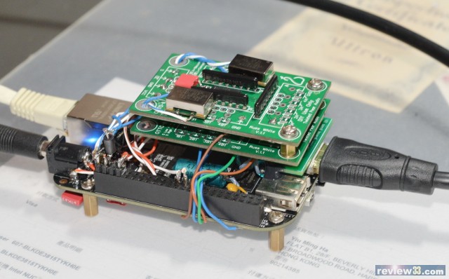
With the botic drivers and MPD supporting native DSD, I tried to know how the serial DSD data can be used for classical SDIF connection using a mastering version of Mytek Stereo 192 DAC equipped with SDIF digital inputs and iD, a clock generator/distributer from Mutec, Germany, that can provide word clock for SDIF connection and master clock for BBB, as shown in the figures below.

As Mytek has both of WCLK In and Out, the output was used as a reference signal for the iD (44.1K REF1 in the figures on the right) to produce MCLK (shown as WCLK7 22.5792), that may imply the BBB working as a slave.
As seen in the figure on the left, P9_41 connects to the red BNC cable as SDIF-R and P9_30 to the blue one as SDIF-L with MCLK input to P9_25 from the yellow one as described above. The green cable in the middle is the WCLK sent to Mytek (shown as WCLK8 44.1). So you might notice that P9_31 is not used for this SDIF connection.
After that, I switched Mytek to SDIF to check the validity of this connection. With both of SDIF-raw and SDIF-3 settings, the results were quite satisfactory with my DSD128 sources, providing flawless sound quality well comparable to that with my BIII/IIISE systems with BBB-botic.
Have a nice weekend.
twluke
Hi there,
Well, this is just for fun because the thread has been rather quiet for a while
.With the botic drivers and MPD supporting native DSD, I tried to know how the serial DSD data can be used for classical SDIF connection using a mastering version of Mytek Stereo 192 DAC equipped with SDIF digital inputs and iD, a clock generator/distributer from Mutec, Germany, that can provide word clock for SDIF connection and master clock for BBB, as shown in the figures below.
As Mytek has both of WCLK In and Out, the output was used as a reference signal for the iD (44.1K REF1 in the figures on the right) to produce MCLK (shown as WCLK7 22.5792), that may imply the BBB working as a slave.
As seen in the figure on the left, P9_41 connects to the red BNC cable as SDIF-R and P9_30 to the blue one as SDIF-L with MCLK input to P9_25 from the yellow one as described above. The green cable in the middle is the WCLK sent to Mytek (shown as WCLK8 44.1). So you might notice that P9_31 is not used for this SDIF connection.
After that, I switched Mytek to SDIF to check the validity of this connection. With both of SDIF-raw and SDIF-3 settings, the results were quite satisfactory with my DSD128 sources, providing flawless sound quality well comparable to that with my BIII/IIISE systems with BBB-botic.
Have a nice weekend
.twluke
Miero,
Just checking in on the status of the ‘final’ driver. While I’m waiting for the Botic Cape to be available, I’m looking at trying a DIY solution for feeding clocks to the BBB & getting a good I2S signal out. If I read things correctly, your final planned enhancement is to add I2C connectivity and functionality (and of course any problem-fixes).
Also, if I read things correctly, the I2S connection pins have changed from the original release to the current one.
My questions are:
1. What’s your timeline for the final version of the driver that includes I2C functionality?
2. Have you specified the I2C pins? If so, how comfortable these will not change as you move towards the ‘final’ driver?
3. How certain are you that the I2S pins are now set and won’t change?
Knowing this will help me plot my path to a DIY solution that I can trust will be stable until the Botic is available.
THANKS!
Greg in Mississippi
P.S. +1 on the following to Steve Ha:
Hi Steve, that's a very impressive achievement. Is there somewhere we can read up on how you did this, or could you share some more details on this. What clocks did you use and how are you switching the OTTO's? I see some extra caps, what do they do?
Is it some standard HDMI I2S pinout you are using, I didn't realise that was possible, need to looks in to that?
Thanks,
1. What’s your timeline for the final version of the driver that includes I2C functionality?
2. Have you specified the I2C pins? If so, how comfortable these will not change as you move towards the ‘final’ driver?
3. How certain are you that the I2S pins are now set and won’t change?
1. I'd like to release driver with basic I2C functionality one-two-three? weeks after I receive Botic by providing compiled kernel - update by replacing several files on SD card.
2. Yes, P9_17 for SCL and P9_18 for SDA
3. The cape will use pins matching "default mode"; see http://bbb.ieero.com/ for more info.
- Home
- More Vendors...
- Twisted Pear
- Support for Botic Linux driver