Hi,
this thread emerged from here
I recently tried the jung-didden super regulator with a balanced composite omp amp stage and am very pleased with the results, escpecially in the mid and high regions: infinte resolution, it seems.
The bass is a bit soft though (or not enhanced compared to a simple opamp preamp), so I thought, maybe a super-shunt-regulator is the eat&keep solution for my cake....
Jonathan Carr mentioned super shunt sonics here
In the same thread he provided a link to a super shunt, which sadly is dead now.
Yesterday, I found a good source concerning shunt reg
The attachment shows a conceptual sketch to a super-shunt. Is my guessing correct that we need a 'beta-booster' (darlington or the like) between error amp and shunt transistor in order to have sufficient regulation capabilities?
thanks,
Rüdiger
Attachments
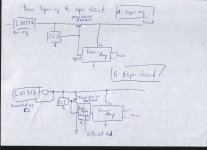
Onvinyl said:[snip]The attachment shows a conceptual sketch to a super-shunt. Is my guessing correct that we need a 'beta-booster' (darlington or the like) between error amp and shunt transistor in order to have sufficient regulation capabilities?
thanks,
Rüdiger
That really depends on the output capability of the error amp. What you normally do is calculate (or precision guess) the variation in shunt current, divide that by the worst-case transistor beta and then compare that to the error amp output current. With a carefull design the shunt only needs to pass the load current VARIATION (plus some constant bias DC current), not, as in a series reg, the total load current, so its requirements are more relaxed than for the series pass transistor.
Jan Didden
Re: Re: Super Shunt topology: any hints?
Are you really sure about this? Could you develop this statement a bit?janneman said:With a carefull design the shunt only needs to pass the load current VARIATION (plus some constant bias DC current), not, as in a series reg, the total load current, so its requirements are more relaxed than for the series pass transistor.
Re: Re: Super Shunt topology: any hints?
hi Jan,
Does that mean, that the shunt does *not* shunt noise, ripple residuals and small variations of the voltage source (psu)? I was thinking -apparently wrong- that the additional Hfe is needed for that (so a fast&high bandwith error amp would be very beneficial in a shunt)?
Would that job left to the CCS that sets the total amount of current (both shunt transistor and load)?
Rüdiger
hi Jan,
janneman said:
With a carefull design the shunt only needs to pass the load current VARIATION (plus some constant bias DC current), not, as in a series reg, the total load current, so its requirements are more relaxed than for the series pass transistor.
Jan Didden
Does that mean, that the shunt does *not* shunt noise, ripple residuals and small variations of the voltage source (psu)? I was thinking -apparently wrong- that the additional Hfe is needed for that (so a fast&high bandwith error amp would be very beneficial in a shunt)?
Would that job left to the CCS that sets the total amount of current (both shunt transistor and load)?
Rüdiger
Re: Re: Re: Super Shunt topology: any hints?
Well, with the series CCS, any load current variation causes a Vout variation and the shunt then draws extra (or less) current to bring the total back so that Vout remains constant. So the shunt really only draws the load current variation.
Noise etc from the input side works similarly: it comes in as noise CURRENT through the CCS and thus adds or subtracts from the load current, and the correction mechanism is than the same as described above.
The input noise current variation is small to begin with, and the shunt can use the very large CCS impedance to work against so that is easily corrected. I think the shunt noise itself is larger; just a hunch.
Edit: The dynamic impedance for the shunt to work against is the CCS in parallel with the load so in both cases the work the shunt has to do is the same.
Jan Didden
Onvinyl said:hi Jan,
Does that mean, that the shunt does *not* shunt noise, ripple residuals and small variations of the voltage source (psu)? I was thinking -apparently wrong- that the additional Hfe is needed for that (so a fast&high bandwith error amp would be very beneficial in a shunt)?
Would that job left to the CCS that sets the total amount of current (both shunt transistor and load)?
Rüdiger
Well, with the series CCS, any load current variation causes a Vout variation and the shunt then draws extra (or less) current to bring the total back so that Vout remains constant. So the shunt really only draws the load current variation.
Noise etc from the input side works similarly: it comes in as noise CURRENT through the CCS and thus adds or subtracts from the load current, and the correction mechanism is than the same as described above.
The input noise current variation is small to begin with, and the shunt can use the very large CCS impedance to work against so that is easily corrected. I think the shunt noise itself is larger; just a hunch.
Edit: The dynamic impedance for the shunt to work against is the CCS in parallel with the load so in both cases the work the shunt has to do is the same.
Jan Didden
Re: Re: Super Shunt topology: any hints?
0 - max current for the shunt regulator
0 - max current for the series regulator
What is the difference?
0 - far from max current for the shunt regulator
0 - far from max current for the series regulator
Relax, in what way? I can't see the difference really.
Compare this:janneman said:With a carefull design the shunt only needs to pass the load current VARIATION (plus some constant bias DC current), not, as in a series reg, the total load current, so its requirements are more relaxed than for the series pass transistor.
0 - max current for the shunt regulator
0 - max current for the series regulator
What is the difference?
0 - far from max current for the shunt regulator
0 - far from max current for the series regulator
Relax, in what way? I can't see the difference really.
Re: Re: Re: Super Shunt topology: any hints?
Suppose you have a load of 1A, that varies with the signal from 0.8 to 1.2 amp. The series reg has to carry min 0.8, max 1.2 amps.
Same load for shunt, the shunt only has to carry from 0 to 400mA. It is a bit extreme admittedly, but the difference is clear.
Unless you have a fully class B load, then there is no difference, indeed.
Jan Didden
peranders said:
Compare this:
0 - max current for the shunt regulator
0 - max current for the series regulator
What is the difference?
0 - far from max current for the shunt regulator
0 - far from max current for the series regulator
Relax, in what way? I can't see the difference really.
Suppose you have a load of 1A, that varies with the signal from 0.8 to 1.2 amp. The series reg has to carry min 0.8, max 1.2 amps.
Same load for shunt, the shunt only has to carry from 0 to 400mA. It is a bit extreme admittedly, but the difference is clear.
Unless you have a fully class B load, then there is no difference, indeed.
Jan Didden
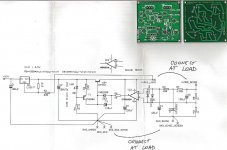
Peranders, Jan,peranders said:Rüdiger, if you want to add some "super" to your regulator you must drive the main shunt transistor with a class A stage. Like the series regulator.
my superreg-board hasn't this transistor (T2 in ALW circuit), only a 10R resistor. Boardwise, it is doable to drop one in. Should I?
Rüdiger
Onvinyl said:
Peranders, Jan,
my superreg-board hasn't this transistor (T2 in ALW circuit), only a 10R resistor. Boardwise, it is doable to drop one in. Should I?
Rüdiger
I don't know the circuit, but if it add loop gain and remains stable, why not? The proof of the pudding...
Jan Didden
That suprises me a bitjanneman said:
I don't know the circuit, but if it add loop gain and remains stable, why not? The proof of the pudding...
Jan Didden
You are namend as author along with walt jung

Attachments
Onvinyl said:
That suprises me a bit
You are namend as author along with walt jung
Well, you mention the ALW circuit, I don't have that in my head. And I thought you were still on shunts. And the schematic you show doesn't have a T2 IISC. So what should I say?

Jan Didden
I'm sorry, my aim was to discuss if its useful to tweak the super reg into a super shunt. And yes, my actual circuit hasn't T2, that's why I asked for both, series and shunt, and here you were confused. I apologize!janneman said:
Well, you mention the ALW circuit, I don't have that in my head. And I thought you were still on shunts. And the schematic you show doesn't have a T2 IISC. So what should I say?
Jan Didden
Rüdiger
I'm not . I know what your idea is. 
As you have noticed (Jan) there are two basic "super regulators". One with no extra emitter follower and one with. Walt did add this in one of his articles later but I don't know when. Was it EDN?
Mr Kaneda had it in 1977.
Rüdiger, which are the basic data of your regulator?
Max output current
Prefered idle current (power loss)
Min-Max input voltage
Min-Max outout voltage
Positive - Negative voltage
Active or passive (=resistor) current source
Preregulator of some sort
. I know what your idea is. As you have noticed (Jan) there are two basic "super regulators". One with no extra emitter follower and one with. Walt did add this in one of his articles later but I don't know when. Was it EDN?
Mr Kaneda had it in 1977.
An externally hosted image should be here but it was not working when we last tested it.
Rüdiger, which are the basic data of your regulator?
Max output current
Prefered idle current (power loss)
Min-Max input voltage
Min-Max outout voltage
Positive - Negative voltage
Active or passive (=resistor) current source
Preregulator of some sort
Per-Anders,
Can be designed, since it is not a finished project. Maybe it is fed alone through pi-filtered psu (like I have it now),
but if experiments show that getting rid of batteries in the first stage also enhances performance, there might be a preregulator.
Rüdiger
I use it for this so with opa627 and ad811 it needs 60mA per channel, so 120mA. Under all expected load conditions, it should not need more, because it is class-A biased. Please correct should I need more safety margin.peranders said:
Rüdiger, which are the basic data of your regulator?
Max output current
It is said that you should have at least 1:1 (shunt : load) so I'd say both the shunt and the current source shall be capable of 300mA to be safe.
Prefered idle current (power loss)
It can be designed as necessary, at the moment I have 28V in
Min-Max input voltage
+/- 15Volt
Min-Max outout voltage
Active
Active or passive (=resistor) current source
Preregulator of some sort
Can be designed, since it is not a finished project. Maybe it is fed alone through pi-filtered psu (like I have it now),
but if experiments show that getting rid of batteries in the first stage also enhances performance, there might be a preregulator.
Rüdiger
Hi a,aparatusonitus said:My turn now, Masao Noro style Super-Shunt Regulator
Best, a
what a nice approach!
Any chances to get the part values?
Rüdiger
- Status
- This old topic is closed. If you want to reopen this topic, contact a moderator using the "Report Post" button.
- Home
- Amplifiers
- Power Supplies
- Super Shunt topology: any hints?