So you didn't really think it trough or did any back-of-the-envelop calculations. You didn't take in account h fact that now the power supply is in a different class. You didn't consider that maybe 15,000uF is not optimal, maybe 50,000 is needed. Or 5,000. Or none.
Maybe you felt it a nice day for some trolling, what with the storm outside?
Jan
Maybe you felt it a nice day for some trolling, what with the storm outside?
Jan
... mmm, but the super regulator has a much, much lower impedance than the cap.I would keep C2. The 15mF (or 10mF) maintains a low impedance for the bias voltage to a low frequency.
At 50 Hz you will get 4.7 ohms and the regulator will have micro ohms or at least some milliohms.
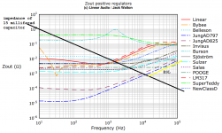
Here is some measured data showing the output impedance of several voltage regulators, versus frequency.... mmm, but the super regulator has a much, much lower impedance than the cap.
At 50 Hz you will get 4.7 ohms and the regulator will have micro ohms or at least some milliohms.
I've overlaid the impedance-vs-frequency curve of a 15 millifarad (fifteen thousand microfarad) capacitor in black. If the capacitor's equivalent series inductance (ESL) is 10 nanohanries, its self resonant frequency is 13 kilohertz and the impedance begins to rise as shown in yellow.
For almost all of these regulators, including the venerable LM317, the regulator's impedance is much, much lower than the 15 millifarad capacitor's impedance, below 1 kilohertz. Just as peranders said.
_
Attachments
Here is some measured data showing the output impedance of several voltage regulators, versus frequency.
I've overlaid the impedance-vs-frequency curve of a 15 millifarad (fifteen thousand microfarad) capacitor in black. If the capacitor's equivalent series inductance (ESL) is 10 nanohanries, its self resonant frequency is 13 kilohertz and the impedance begins to rise as shown in yellow.
For almost all of these regulators, including the venerable LM317, the regulator's impedance is much, much lower than the 15 millifarad capacitor's impedance, below 1 kilohertz. Just as peranders said.
_
Mbe I should just send you the data!
I wouldn't call the LM317 "venerable" any more, perhaps "veteran" or "vestigial".
C2 is on the bias reference voltage. That reference is separated from the Power Source by two high value resistors R2 & R3.... mmm, but the super regulator has a much, much lower impedance than the cap.
At 50 Hz you will get 4.7 ohms and the regulator will have micro ohms or at least some milliohms.
Last edited:
Any variation on the bias voltage will get mixed with the audio signal.
If you need low noise and/or low interference pickup, then the bias voltage needs a low impedance.
As I read it, N.Pass inserted C2 to achieve that end.
I do not see C2 as being there to improve the power supply impedance.
I seem to recall that N.Pass allowed for some variation in the value of C2. I don't recall any advice to remove it.
The bias voltage can only vary if the bias current varies. That won't happen - see the schematic.
NP knows that many users would use a horribly noisy supply, therefor heroic measures are required to get a clean bias in all cases. With a SilentSwitcher, the supply and bias is cleaner than any caps can come close to.
Please print this and paste it over your desk (not you Kinku):
"Engage brain before operating keyboard".
thanks, Jan
Last edited:
Sorry for being ignorant , but why would the two resistors after a low noise power supply making a voltage divider would get extra help from a capacitor. Perhaps Nelson did that as the supply he uses is a simple CRC one?
You show more insight than some would-be gurus here.
Jan
Jan , thanks!
Does the pass transistor need a heatsink for current draw by B1 at 40 -50ma, and 18V?
Depends on the regulator input voltage. If you have say 23V input and the reg set for 18V out, that's just 5V * 0.05A = 0.25W. That's nothing.
But if your input voltage is higher and it gets to a watt or so, I would use an on-PCB heatsink.
Jan
Hi, the 6.8V zener is used to float the OPAs output nicely in the (approximately) middle of the single supply voltage. For example, I used an 8.2V zener for a 17V version of the superreg.
Spot on.
As to what is often called voltage overhead, something like 5V would be fine, but you can get down to a couple of volts. And remember, the input voltage has ripple so the minimum headroom is counted from the botttom of the ripple, not from the average (measured) input voltage!
Jan
Hi, the 6.8V zener is used to float the OPAs output nicely in the (approximately) middle of the single supply voltage. For example, I used an 8.2V zener for a 17V version of the superreg.
Sorry,wondering if you can make it a bit more simple. What I understand is a value less than half of required voltage is fine ? So if I am looking for 20 V any zener below 10V forwards voltage rating will work? ( I guess within some reasonable lower limit) straying perhaps from 6.8V?
Well, the opa is supplied with the single voltage that is your regulators output. Therefore the operating range of the output of the opa is from 0V to somewhat lower than the 15V Vout of the reg. To enable (almost) symmetrical swing of the output of the opa, the zener creates a virtual zero-point between 0V and Vout of the reg.
Ah, and to answer your question. For 20V I would choose 9.1V Zener. Even a higher value, above the mathematical middle is ok. But usually you stay away from the higher voltage zener. If I recall that correctly the higher voltages have worse noise figures. But I haven't really thought about noise at this point of the circuit.
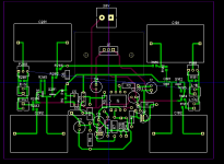
Made a layout,power supply with TH components and B1 with smd for differentiating better. Part number for power supply same as original v2.3 schematic from Jan's positive reg except R16 replaced by R8. Please recommend improvements
Picked this diode for D2
BZX84J-B7V5,115 Nexperia | Mouser
Picked this diode for D2
BZX84J-B7V5,115 Nexperia | Mouser
Attachments
- Home
- The diyAudio Store
- Super Regulator