If the resistor values are what you built I would expect to see the LM329 voltage at the + input of the op amp (about 6V9 as I remember) and the close to the same voltage on the - input. For that to happen the output needs to be about 2.4 times that determined by the ratio of the 3K6 resistor and the 4K99 plus 100R, which is about 16V7.
these are my resistors value on the pcb:
These are the value of my resistors (target 12v output):
R6 = 12k
R7 = 8.87k
If the resistor values are what you built I would expect to see the LM329 voltage at the + input of the op amp (about 6V9 as I remember) and the close to the same voltage on the - input. For that to happen the output needs to be about 2.4 times that determined by the ratio of the 3K6 resistor and the 4K99 plus 100R, which is about 16V7.
His schematic is not up to date. His resistor values are 7.5k and 12k. At least that's what he says.
Jan
it would help alot if you had an understanding of how it operates. The LED and Q1 form a current source to supply base current to the series pass transistor. The reference voltage across the LM329 is compared with a fraction of the output voltage as determined by R6 and R7. When things are in balance that voltage matches the reference voltage. If the output rises the op amp pulls more of the Q1 current away from the Q2 base to cause the output voltage to go down again. A similar action occurs if the output voltage droops. The op amp will pull less current from the Q1 current so the Q2 gets more.
If R7=12K and R6=8.87K doesn't produce the correct output voltage, the circuit has other problems. It is not normal for the LED to just blink at turn on and turn off. The schematic seems to indicate that there is 15.6 volts across the LM329. It should be 6.9 volts if the LM329 is working and not blown up. Make sure + and S+ are securely connected together. Same for - and S-.
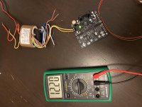
Now it's working.
The problem was related to the footprint of the LM329. It's inverted. So I turned of 180° the LM329 and now it's work.
I don't understand why the output is 12.2v and not 12v.... but I'm quite satisfied, ...this is my first pcb.
Thank you very much for your value help!
The problem was related to the footprint of the LM329. It's inverted. So I turned of 180° the LM329 and now it's work.
I don't understand why the output is 12.2v and not 12v.... but I'm quite satisfied, ...this is my first pcb.
Thank you very much for your value help!
Attachments
Last edited:
At 12.2 volts the output is well within 2% of the 12 volt target. This is quite good considering the LM329 is a 5% accurate part and the resistors probably have a 1% tolerance. By the way, 12K is not a standard 1% resistor value; the standard 1% value is 12.1K so that may be shifting the output voltage a bit. Using 12K as you specified, perfect component values yield an output voltage of 12.058 volts so your result is very close to ideal.
At 12.2 volts the output is well within 2% of the 12 volt target. This is quite good considering the LM329 is a 5% accurate part and the resistors probably have a 1% tolerance. By the way, 12K is not a standard 1% resistor value; the standard 1% value is 12.1K so that may be shifting the output voltage a bit. Using 12K as you specified, perfect component values yield an output voltage of 12.058 volts so your result is very close to ideal.
Thank you for the explication
Sounds like a great opportunity to experiment with advanced features of search engines!
Hey Bing, find me all web pages on the diyAudio site, which contain the character string "Super Regulator" (with or without capital letters), AND which contain the character string "LTSPICE", AND which contain the substring ".asc"
Hey Bing, find me all web pages on the diyAudio site, which contain the character string "Super Regulator" (with or without capital letters), AND which contain the character string "LTSPICE", AND which contain the substring ".asc"
Do you think I didn't already look for super-regulator simulations? Of course I did.
The one I found does not use the AD opamps or the others.
If I'm not wrong I already loaded them on this thread. If not, here go some of them, some with unusual opamps like the LF411 or OP27.
Except for noise on the 411, it did quite well.
Unfortunately no models for AD825 or AD817. Not sure if the LT1028 should be something like the AD797 on the simulation. But I did try it too, also the LT1115, which is considered quite similar to it.
What I mean is an exact simulation of the "official" circuit.
Attachments
Why can't you just take one of the sim files and change it to the 'official' circuit? That's much faster than spending lots of time to find something that probably isn't there to begin with.
Remove .txt from the model and the symbol.
Jan
Remove .txt from the model and the symbol.
Jan
Attachments
Last edited:

- Home
- The diyAudio Store
- Super Regulator