Interesting. Shielding against RFI/EMI?
My look was mostly to hum and capacitive feedback.
jd
The pcb has ground planes on all four layers where two of them are only ground, no traces and I have also add a cap between output of the opamp and the - input, just in case. I haven't had any opportunity to harass the pcb with RF.
The LM317 has decoupled feedback but the gain is only two so the impact of this cap will be minor I should think.
The LM317 has decoupled feedback but the gain is only two so the impact of this cap will be minor I should think.
Last edited:
The pcb has ground planes on all four layers where two of them are only ground, no traces and I have also add a cap between output of the opamp and the - input, just in case. I haven't had any opportunity to harass the pcb with RF.
The LM317 has decoupled feedback but the gain is only two so the impact of this cap will be minor I should think.
I must publicly apologize here to P-A. He send me a board of his reg to evaluate but I still haven't found the time to do it. I did note the excellent pcb he developed.
P-A, if you want me to send the board back or to another 'tester' let me know.
jd
 and I would be pleased if you would test it but feel no pressure.
That's good to know. Thanks.
The lower cost is one reason I choose the LME49720. But even it was out of stock at the time I was building.
So I ended up with the OPA1611 as a place holder. It seems to be happy in the circuit.
Wonder how much better one of the "superb" opamps would be?
The lower cost is one reason I choose the LME49720. But even it was out of stock at the time I was building.
So I ended up with the OPA1611 as a place holder. It seems to be happy in the circuit.
Wonder how much better one of the "superb" opamps would be?
Mr jackinnj has once again done some noise measurements and my pcb behaves quite nicely although the difference is small.
The Invisus regulator is a 185 dollar product.
Noise is only one parameter. It would have been fun to know the output impedance as a function of the frequency.
The Invisus regulator is a 185 dollar product.
Noise is only one parameter. It would have been fun to know the output impedance as a function of the frequency.
Attachments
Nice results! Considering that at 1kHz the difference in noise between the best and the worst seems 200nV, the real practical difference MIGHT be in the output impedance. As noon as you wiggle the load there'll be a lot more than microvolts ripple at the output. It would be nice to see, at least Zout at a few frequencies, 100, 500, 1k, 3k, 10k, 15k?
The impedance measurement setup used by Jung isn't specified in the articles -- and I blew up some really nice, high value caps trying to use them to inject the 50mA "perturbation" signal! The 600 ohm Jensen transformer I have shows significant saturation with only a bit of DC.
I am able to measure below 1 milliOhm, but not yet down to the 10's of microOhms:
I had my first AD797 SuperReg go into oscillation -- it was outside its metal case -- the current was much higher than I had expected, no problem showed up on the AP Analyzer, but putting it on the 'scope showed a mean oscillation around 1.4MHz.
I am able to measure below 1 milliOhm, but not yet down to the 10's of microOhms:
An externally hosted image should be here but it was not working when we last tested it.
I had my first AD797 SuperReg go into oscillation -- it was outside its metal case -- the current was much higher than I had expected, no problem showed up on the AP Analyzer, but putting it on the 'scope showed a mean oscillation around 1.4MHz.
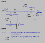
For what it's worth, I've attached the mosfet load setup that I've tried. The mosfet makes a current limiter, with R13 setting the DC current. The AC current component can be inserted with a signal generator.
I just don't know if this is correct for measuring the output impedance.
I just don't know if this is correct for measuring the output impedance.
Attachments
The impedance measurement setup used by Jung isn't specified in the articles -- and I blew up some really nice, high value caps trying to use them to inject the 50mA "perturbation" signal! The 600 ohm Jensen transformer I have shows significant saturation with only a bit of DC.
I am able to measure below 1 milliOhm, but not yet down to the 10's of microOhms:
Let's say you had a 100 micro ohms supply. Injecting a 50mA signal would impose a 5uV ripple at the output of your supply. 50 micro ohms supply would have about 2.5uV at the output. I thought you were able to measure such small noise using your low noise amp?
The impedance measurement setup used by Jung isn't specified in the articles -- and I blew up some really nice, high value caps trying to use them to inject the 50mA "perturbation" signal! The 600 ohm Jensen transformer I have shows significant saturation with only a bit of DC.
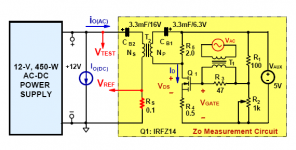
Have a look at the figure attached. The transformer doesn't need to handle any DC.
This is out of the paper I mentioned before,
http://www.deltartp.com/dpel/dpelconferencepapers/33.3_10275.pdf
Attachments
I simmed the circuit -- you've got a pole with the leakage inductance of the transformer T2 to contend with -- I measure mine at 800uH -- so the use-able frequency is limited. I think a more traditional current driver. To make it easier, I have a bipolar supply to drive the MOSFETs. I'll try it....
I simmed the circuit -- you've got a pole with the leakage inductance of the transformer T2 to contend with -- I measure mine at 800uH -- so the use-able frequency is limited. I think a more traditional current driver. To make it easier, I have a bipolar supply to drive the MOSFETs. I'll try it....
For the original article I used the generator of the AP S1 feeding a capacitor (electrolytic) coupled current into the reg output. You can use the genetaor output Z (like 150 or 600 ohms) as the voltage to current converter. Then measure the resuting voltage at the reg output, of course. The max AP generator Vout is about 15V RMS, and with 150 ohms that allows up to 100mA ac current. Should be enough.
There is an AP app note for measuring amplifier output Z but the concept is the same (I think it is app note 1 even).
jd
- Status
- This old topic is closed. If you want to reopen this topic, contact a moderator using the "Report Post" button.
- Home
- Amplifiers
- Power Supplies
- Super Regulator, collecting the facts